Electrically powered brake system and control unit for electrically powered brake system

Inactive Publication Date: 2006-07-27
HITACHI LTD
View PDF4 Cites 100 Cited by
  • Summary
  • Abstract
  • Description
  • Claims
  • Application Information

AI Technical Summary

Benefits of technology

[0011] Since the electrically powered brake system of the present invention configured as described above performs a diagnosis of elements constituting the electrically powered brake system to detect an abnormality during actuation of the parking brake, a failure location can be diagnosed before a vehicle is driven, and generation of an unintended braking force during driving can be prevented. As a result, safe driving of a vehicle can be achieved.
[0012] As a preferable aspect of the electrically powered brake system, the motor is supplied with a voltage from an electric power supply via switching means such as a relay as the element, and the diagnosis means performs a diagnosis of the switching means. The electrically powered brake system configured as such can perform a diagnosis of switching means such as a relay for supplying an electric power from the electric power supply to the motor to detect a failure, thus making it possible to prevent a braking force abnormality by a failure of the switching means when a vehicle is driven.
[0013] As a preferable specific aspect of the electrically powered brake system, the electrically powered brake system has a braking force sensor

Problems solved by technology

However, the operation of the fail safe described in Patent Document 1 is actuated only in a state in which a failure is detected and controll

Method used


Image

  • Electrically powered brake system and control unit for electrically powered brake system
  • Electrically powered brake system and control unit for electrically powered brake system
  • Electrically powered brake system and control unit for electrically powered brake system

Examples


Embodiment Construction

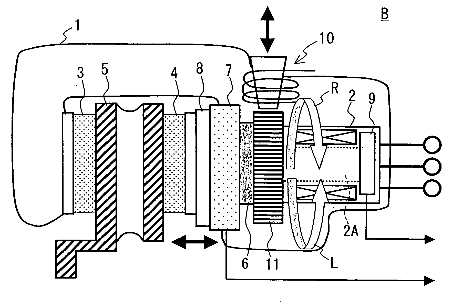
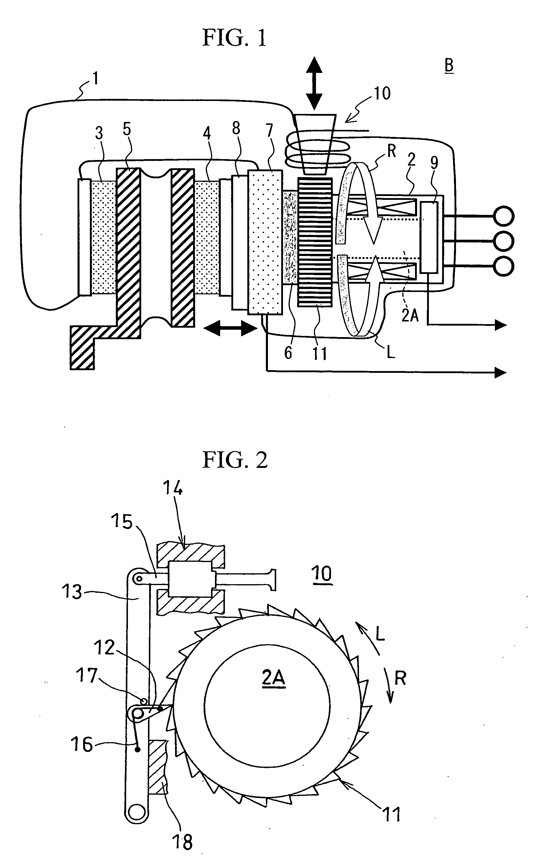
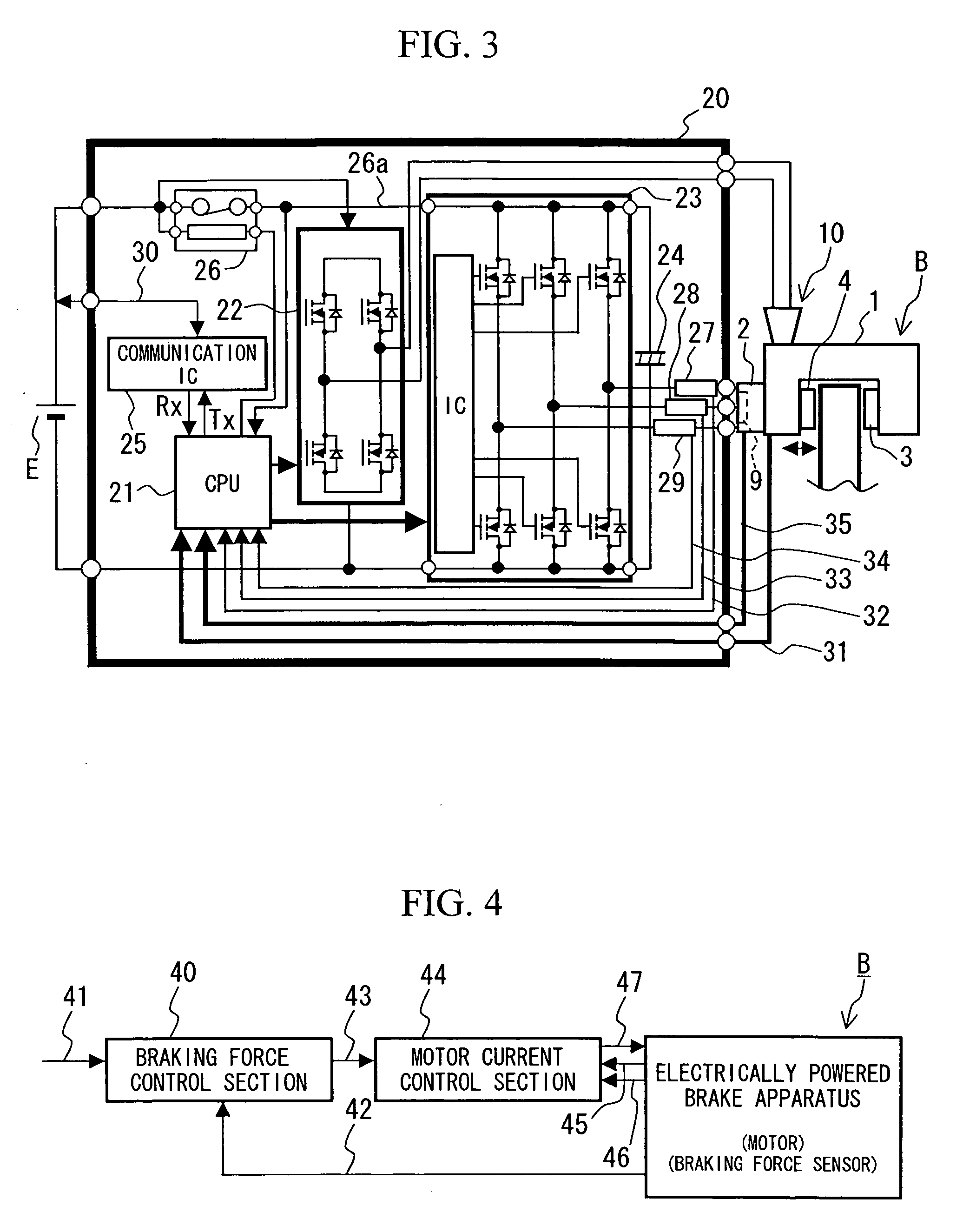
[0060] One embodiment of an electrically powered brake system according to the present invention will be described in detail below based on the drawings. FIG. 1 is a view of the configuration of essential parts of an electrically powered brake apparatus according to this embodiment, FIG. 2 is a view of the configuration of essential parts of a locking mechanism making the electrically powered brake apparatus of FIG. 1 function as a parking brake, FIG. 3 is a block diagram showing the configuration of a control unit controlling the electrically powered brake system, FIG. 4 is a block diagram showing the specifics of control performed in a CPU of FIG. 3, FIG. 5 is a chart showing braking force data, an actual braking force, a motor rotation angle, each phase current of a motor and an effective current of the motor, and FIG. 6 is a schematic diagram of an electrically brake system mounted on a vehicle.

[0061] In FIGS. 1 and 2, the electrically powered brake apparatus B has a caliper 1 ...


PUM


Abstract

An electrically powered brake system capable of performing a self-diagnosis of elements of the electrically brake system to diagnose a failure before a vehicle is driven is provided. The electrically powered brake system having a parking brake having a conversion mechanism 6 converting a rotary motion of a motor 2 into a linear motion, propelling a piston 7 according to the rotation of a rotor 2A of the motor 2 by the conversion mechanism, pressing brake pads 3 and 4 against a disc rotor 5 by the piston to generate a braking force, and retaining the braking force by a locking mechanism 10 has a control unit 20 performing a diagnosis of elements constituting the system during actuation of the parking brake. The control unit performs a diagnosis of a fail safe relay 26 receiving the supply of electric power of the motor, and performs diagnoses of a braking force sensor 8, a rotation angle detecting sensor 9 and a current sensor.

Description

BACKGROUND OF THE INVENTION [0001] 1. Field of the Invention [0002] The present invention relates to a brake system which is used in an automobile or the like, and particularly to an electrically powered brake system electrically generating a braking force and a control unit performing a failure diagnosis of the electrically powered brake system. [0003] 2. Background Art [0004] As a fail-safe for a failed wheel which suffered a failure of a control system including software and hardware in an electrically powered brake using a motor as a braking force source, fail-open functions of removing a braking force of the failed wheel to prevent a vehicle from being braked have been proposed. The mechanical specifics of these functions are disclosed in Patent Document 1 (JP Patent Publication (Kokai) No. 2003-14014) and others. They are based on a method in which an electrically powered brake actuator is made to completely stop control and input of electrical energy is blocked to remove a br...

Claims


Application Information

Patent Timeline
IPC IPC(8): B60T8/88F16D65/18
CPCB60T8/885B60T13/741B60T17/22B60T2270/406B60T2270/414F16D2121/24F16D2127/06F16D2129/08
Inventor KURAMOCHI, YUICHIINNAMI, TOSHIYUKI
Owner HITACHI LTD
Why Eureka
Try Eureka