Brake by-wire actuator

a technology of actuators and wires, applied in the direction of braking systems, braking components, transportation and packaging, etc., to achieve the effect of low cost, compact arrangement, and low requirement of sensors

Inactive Publication Date: 2006-07-27
CONTINENTAL TEVES AG & CO OHG
View PDF8 Cites 109 Cited by
  • Summary
  • Abstract
  • Description
  • Claims
  • Application Information

AI Technical Summary

Benefits of technology

[0033] A particularly great advantage of the invention is achieved in that in the event of failure of electric actuating signals of an active vacuum brake booster, in particular in the event of failure of an energy supply of the brake actuation device, the booster can be actuated directly mechanically, with the result of having provided a secured fallback mode when the electronics fails. In this case, a pneumatic booster operates like a conventional pneumatic brake booster, while the hydraulic boosting ratio in the master brake cylinder comes into effect in hydraulic boosters.
[0034] A grading of the fallback modes can also be provided in dependence on the sensors available. If, for example, one of two brake circuits fails, boosting can be rated so that higher brake pressure is fed to the intact brake circuit. When the vehicle is in the limit range of driving stability, the use of anti-skid measures such as anti-lock system (ABS) or Electronic Stability Program (ESP) is advisable. Advantageously, the failure of a brake circuit will trigger an alarm to the driver by way of the above-mentioned display elements.
[0035] The brake actuation device of the invention can be employed in a very expedient manner also for ESP functions. As the ESP functionality is based on speed jeopardizing driving stability and requires an actuation on each individual wheel without a request for braking, especially quick pressure pulses at selected wheel brakes are significant. This fact is safeguarded according to the invention because a separate booster such as a pneumatically operating booster in particular, a hydraulic booster, or any other means is connected. Conditions are roughly comparable to traction slip control (TCS) during which traction slip shall be reduced due to braking intervention or engine intervention, as the case may be.
[0036] Further, the brake actuation device of the invention allows actuation of the booster also in dependence on further parameters that occur irrespective of the position of the brake pedal lever, such as ABS, ESP, Intelligent Cruise Control (ICC), TCS, and other signals being triggered by the driving condition of the vehicle or a driver's request such as when starting to drive uphill.
[0037] When an active vacuum brake booster is used, there is no need for a high-pressure accumulator according to the invention, and the brake system is manufactured at low cost and with a compact arrangement. Sensor signals are sent to a central control unit, and the requirement of sensors is generally low. For most of the mentioned functions it is sufficient to use one travel or rotary angle sensor at the brake pedal in order to detect the driver's request, and the travel sensor described for detecting the position of the diaphragm plate and its deviation for the purpose of controlling the booster or for detecting the OHBV case, as well as one hydraulic pressure sensor in at least one brake circuit for determining the actual value in the brake system and for detecting the deviation of the actual value from the driver's request, while taking into account safety provisions and the OHBV mode. When a so-called force-feedback pedal is used, it is possible to assign a rotary angle sensor or travel sensor to the force-feedback actuator (reaction force generator) so that two rotary angle sensors or travel sensors are provided in total in the pedal range, whose signals are sent to the central control unit.
[0038] A pneumatic brake booster may additionally dispose of a pneumatic pressure sensor or differential pressure sensor sensing the pneumatic pressure or a pressure difference between pneumatic chambers.

Problems solved by technology

This behavior is easy to achieve for the by-wire mode in brake-by-wire systems, however, not in the case of a change to a mechanical through grip within a so-called mechanical or hydraulic fallback mode.

Method used


Image

  • Brake by-wire actuator
  • Brake by-wire actuator
  • Brake by-wire actuator

Examples


Embodiment Construction

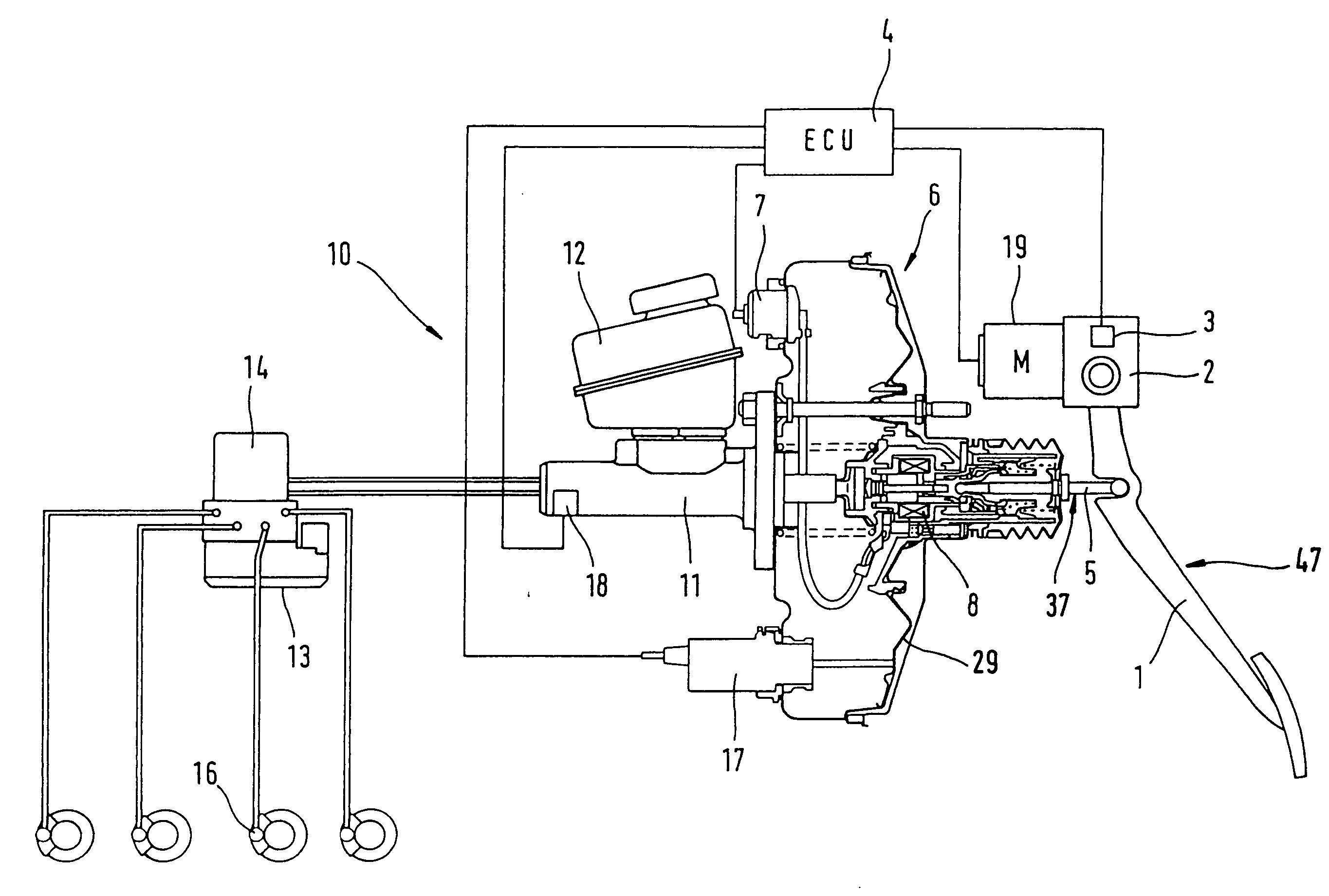
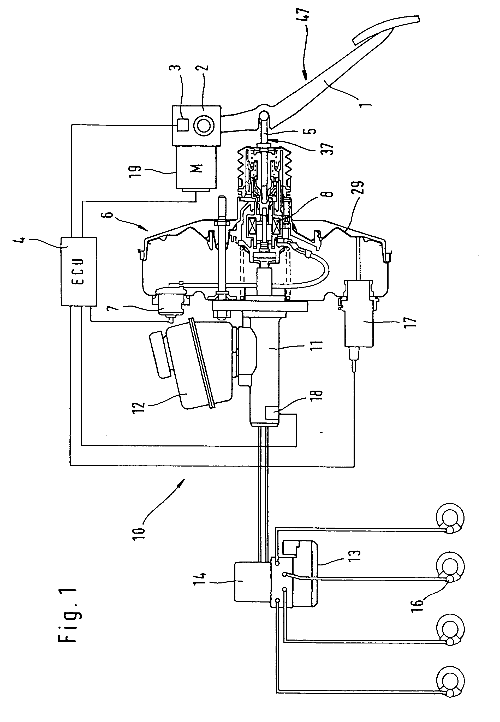
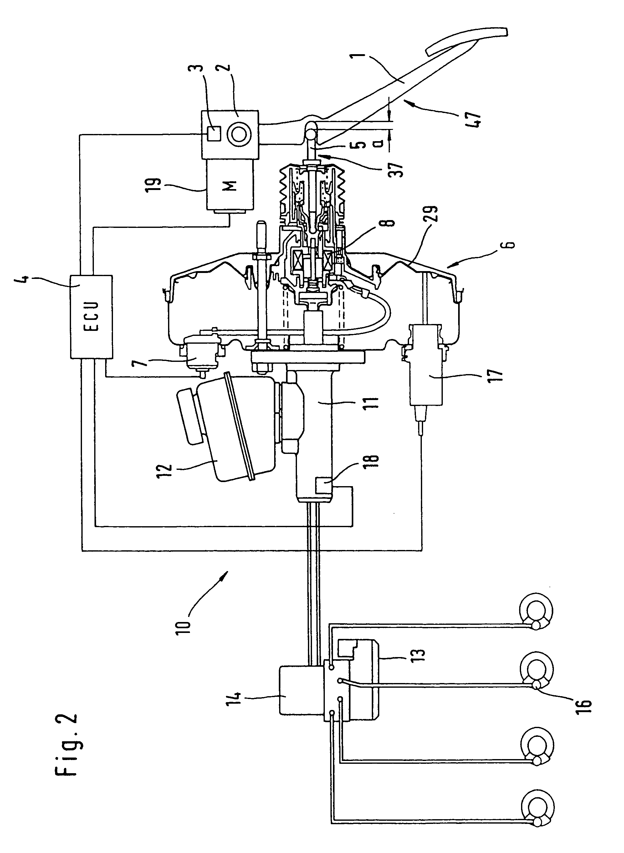
[0051] With reference to FIG. 1, a brake actuation device comprises a brake pedal 1 equipped with a simulator 2. Simulator 2 includes at least one, preferably two redundant actuation sensors 3 whose output signals are sent to an electronic control unit 4 (ECU). The brake pedal 1 can be coupled mechanically to the booster 6 by way of an actuation component 5 of a pneumatic booster 6. A connection of this type is usual in the prior art pneumatic boosters 6 because they are actuated mechanically in analog manner by way of the brake pedal 1 and the actuation component 5. In the case of failure of the electronic unit 4, such an actuation is possible also in the brake actuation device of the invention and provides a reliable fallback mode. The booster 6 can be actuated electrically by an output signal of the electronic circuit 4 by way of a connection 7 in addition to the actuation component 5. This is done by means of a magnetic drive 8 which makes catch at the actuation component 5 and ...


PUM


Abstract

The present invention relates to a brake-by-wire actuator for actuating the brake system of a motor vehicle, comprising a simulator which can be acted upon by a brake pedal, with a signal of an actuation sensor being sent to an electronic control unit which controls a pressure source in response to the signal of the actuation sensor, and wherein an output of the pressure source is connected to a distributor device for the brake force and actuates individual wheel brakes of the vehicle, also comprising means for enabling actuation of the brakes by muscular power within a fallback mode. In order to provide an improved fallback mode in a brake-by-wire actuator, according to the invention, a lost travel is provided between a first actuation component such as a brake pedal in particular or a component articulated at the brake pedal and an actuation component that is connected downstream in the flux of force, in particular an input member, in order to uncouple the first actuation component mechanically from the reactions of force of the motor vehicle brake system in the by-wire mode.

Description

TECHNICAL FIELD [0001] The present invention relates to a brake-by-wire actuator for actuating the brake system of a motor vehicle, comprising a simulator which can be acted upon by a brake pedal, with a signal of an actuation sensor being sent to an electronic control unit which controls a pressure source in response to the signal, and wherein an output of the pressure source is connected to a distributor device for the brake force and actuates wheel brakes, also comprising means for enabling actuation of the brakes by muscular power within a fallback mode. BACKGROUND OF THE INVENTION [0002] A generic brake actuation device has been disclosed already in an electrohydraulic brake system (EHB). The device is based on uncoupling the brake pedal hydraulically from the hydraulic reaction forces of the brake system by the provision of electromagnetic separating valves isolating a master brake cylinder hydraulically from the brake system. The brake pressure in the wheel brakes is controll...

Claims


Application Information

Patent Timeline
Patent Type & Authority Applications(United States)
IPC IPC(8): B60T8/34B60T7/04B60T8/17B60T7/06B60T8/40B60T8/44B60T13/66B60T13/68B60T13/74
CPCB60T7/042B60T7/06B60T8/4077B60T8/441B60T13/686
Inventor VON HAYN, HOLGERSCHONLAU, JURGENRUFFER, MANFREDRITTER, WOLFGANGKLIMES, MILANQUEISSER, TORSTENECKERT, ALFREDVON ALBRICHSFELD, CHRISTIAN ALBRICH
Owner CONTINENTAL TEVES AG & CO OHG
Why Eureka
Try Eureka