Image processing camera system and image processing camera control method

a camera system and image processing technology, applied in the field of image processing camera system and image processing camera control method, can solve the problems of inability to make the camera sharable by approximation, inability to stop the lane-keeping system, and inability to provide reliable system

Active Publication Date: 2006-07-27
HITACHI ASTEMO LTD
View PDF1 Cites 40 Cited by
  • Summary
  • Abstract
  • Description
  • Claims
  • Application Information

AI Technical Summary

Benefits of technology

[0005] An object of the present invention is to provide an image-processing camera system capable of sharing, with high reliability, one image pickup device between multiple application programs.
[0006] Another object of the present invention is to provide a very-easy-to-use image-processing camera system that explicitly displays multiple executable application programs to a user and enables the user to select desired application programs without hesitation.
[0008] This makes highly reliable sharing of one image pickup device among the plural application programs that dynamically vary camera parameters.
[0010] This makes it possible to provide a very-easy-to-use image-processing camera system that explicitly displays plural executable application programs to the user and enables the user to select desired application programs without hesitation.

Problems solved by technology

If this cycle is not strictly observed, system operation will not be allowable since control that uses image processing will be impossible and thus since the system itself will not operate properly and result in malfunction or other unusual states.
Therefore, the camera cannot be made sharable by the approximation of the camera parameters existing at a particular point of time.
The next moment, however, the camera parameters will change, which will make the camera non-sharable and stop the lane-keeping system.
Otherwise, a reliable system will not be obtainable.

Method used


Image

  • Image processing camera system and image processing camera control method
  • Image processing camera system and image processing camera control method
  • Image processing camera system and image processing camera control method

Examples


Embodiment Construction

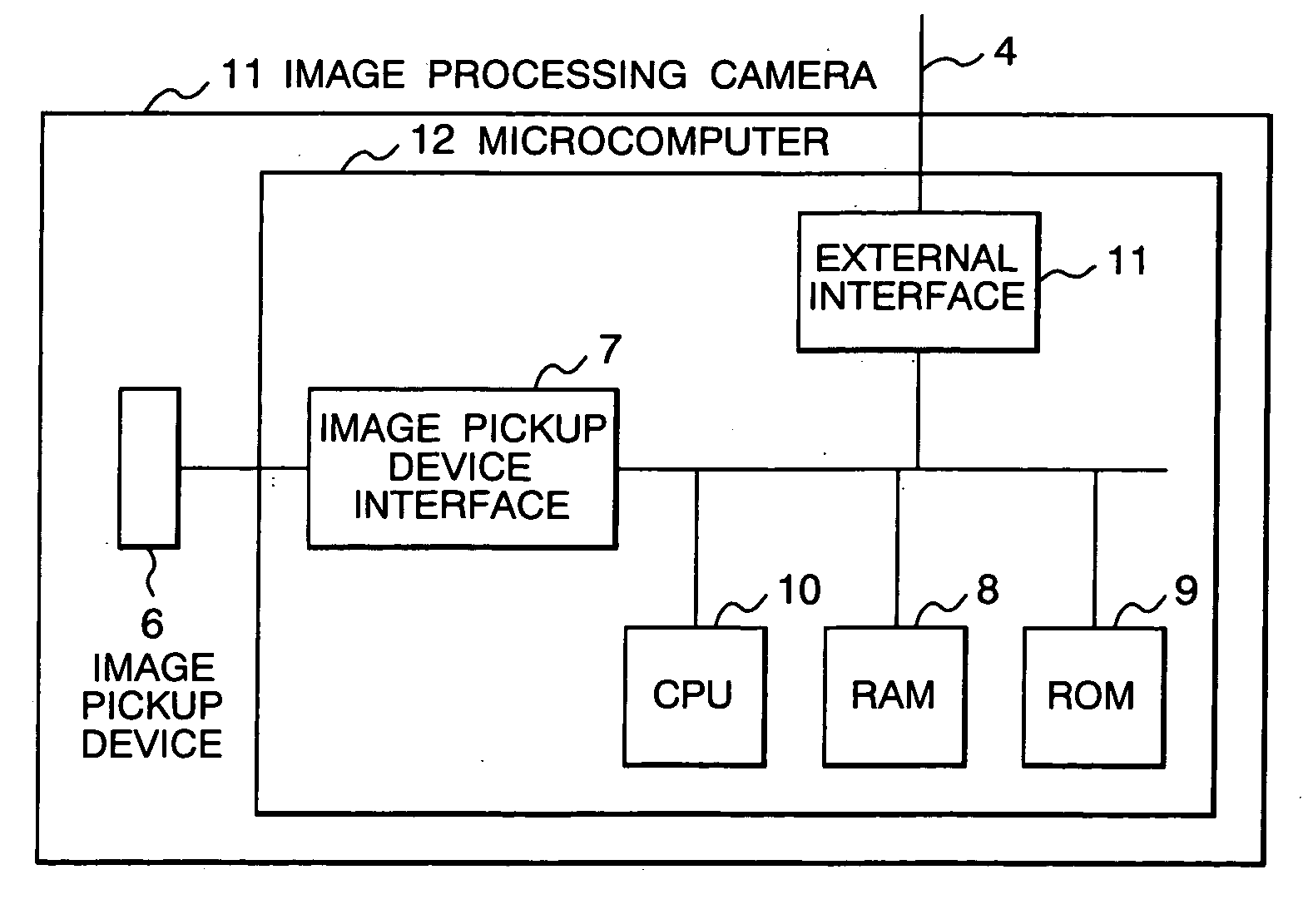
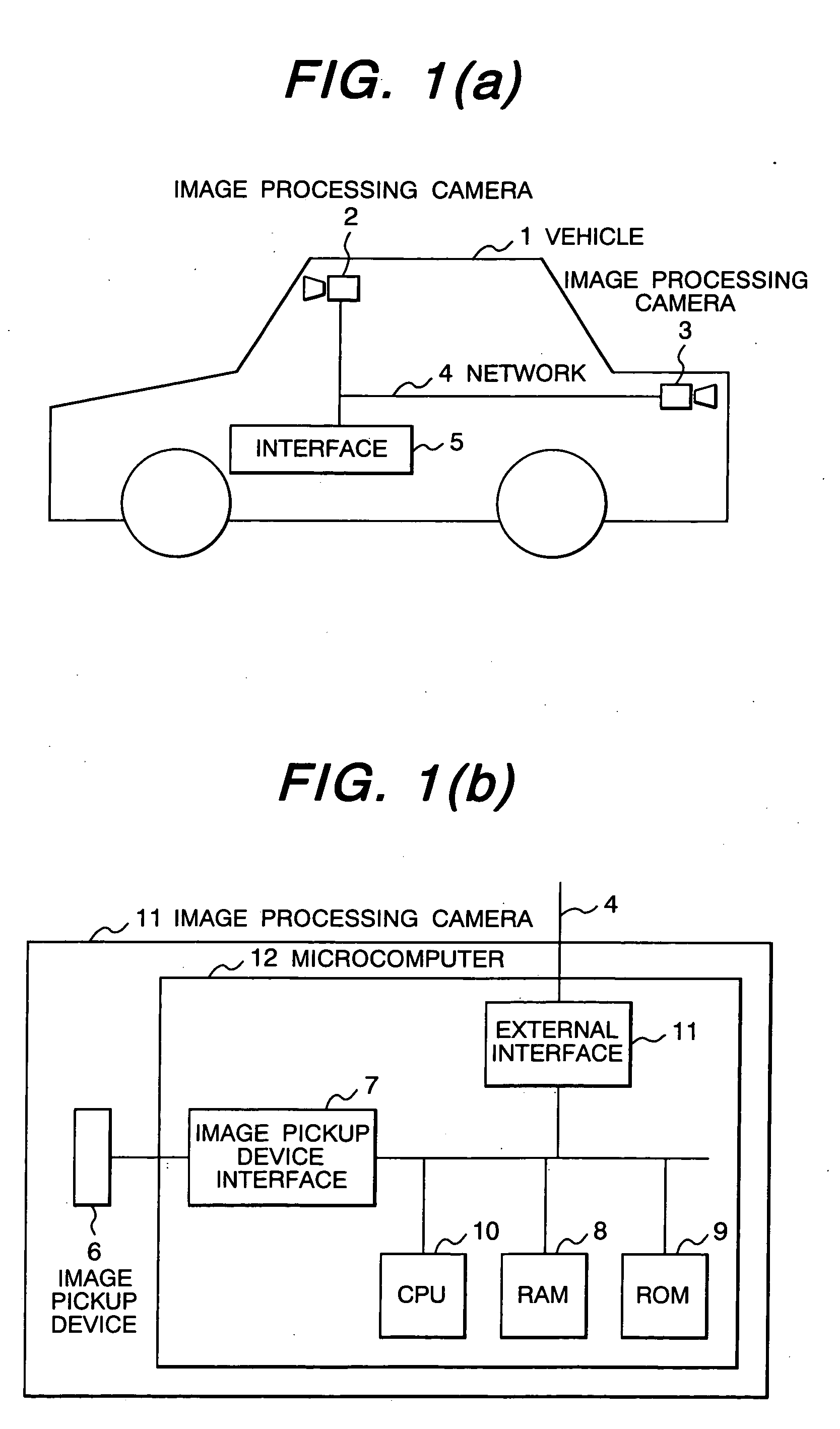
[0030]FIG. 1 shows a schematic block diagram of an automobile-mounted image-processing camera system in an embodiment of the present invention, and a hardware configuration diagram of an image-processing camera. This image-processing camera system realizes such a large number of application programs as described later herein, by using cameras 2, 3 installed in a forward direction and backward direction of an automobile 1. The image-processing cameras 2, 3 are connected to an interface element 5 via a network 4. For the automobile 1, the network 4 can be, for example, a standardized network such as a control area network (CAN), or an access method that only expresses ON / OFF states with a mere electric power line, or any other appropriate form of access. The interface element 5 is a navigation system, a steering wheel, a brake, or any other device that exchanges information with a driver, or is an engine control unit, a global positioning system (GPS), a sensor, or any other device th...


PUM


Abstract

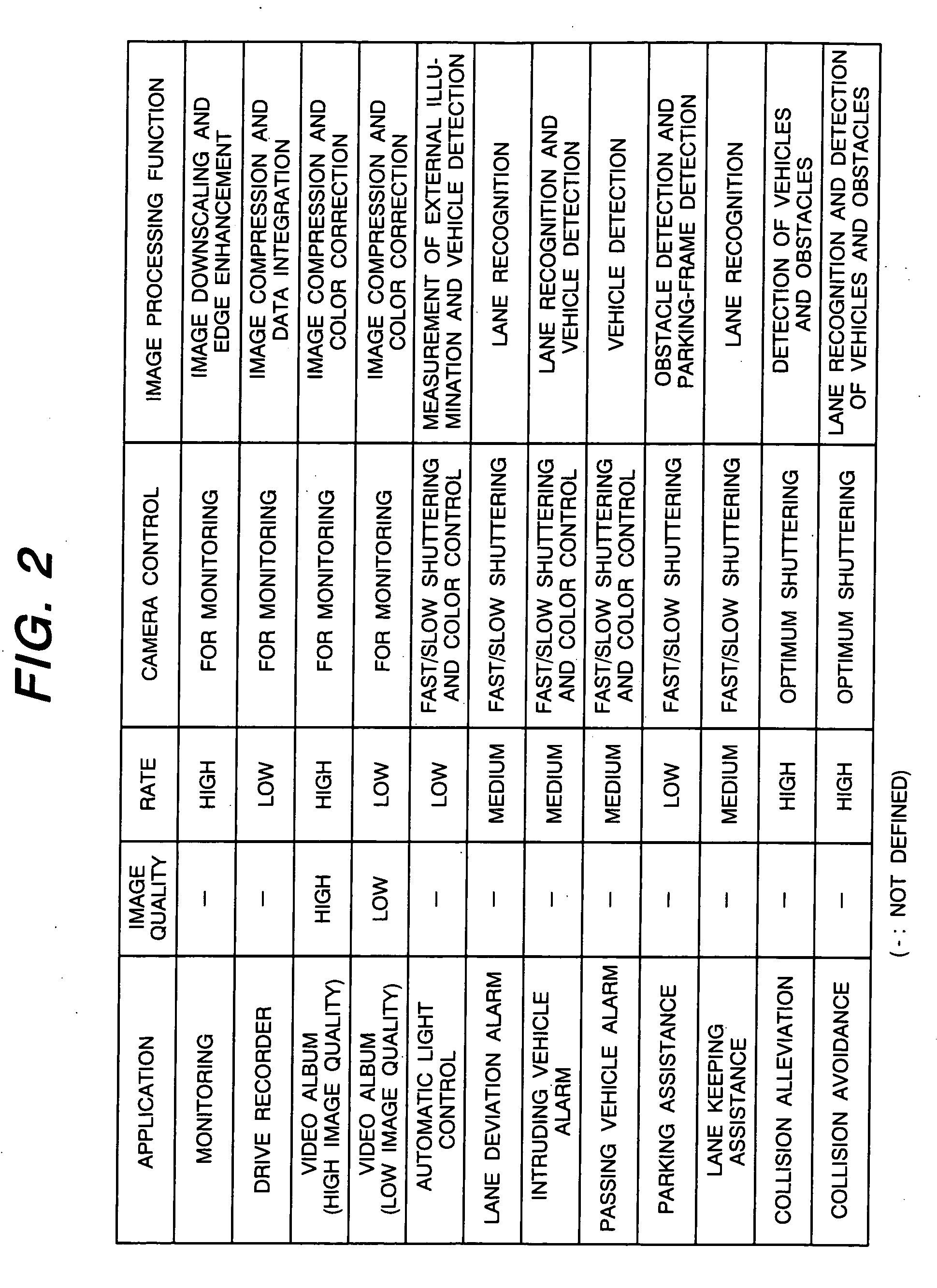
An object of this invention is to make one image pickup device sharable, with high reliability, among the multiple application programs that dynamically vary camera parameters. In order to achieve this object, the invention includes an image pickup device 6 that acquires images, an image pickup device controller 13 that accepts image acquisition requests from the multiple application programs 151 to 15N and controls the image pickup device, an application scheduler 14 that selects application programs to be executed. The invention further includes an element 17 that stores the image data volumes and image data acquisition rates required in the multiple application programs 151 to 15N, an element that selects multiple concurrently executable application programs on the basis of the above image data volumes and image data acquisition rates, and an image acquisition scheduler 14 that determines the timing and intervals at which the multiple executable application programs repeat acquiring image data from one image pickup device without overlapping in terms of time. In addition, an operations section that explicitly presents concurrently executable application programs to a user and commands the startup of these programs is displayed on a navigation screen menu 19. According to this invention, one image pickup device can be shared, with high reliability, among multiple application programs. Also, the user can start up executable application programs without hesitation.

Description

FIELD OF THE INVENTION [0001] The present invention relates to an image-processing camera system sharing one image pickup device for multiple purposes, and to a method of controlling the camera system. BACKGROUND OF THE INVENTION [0002] Image-processing technology has already begun to be applied to surveillance systems intended to detect the intrusion of unwanted persons and / or the occurrence of unusual events, and to vehicle-mounted systems for assisting safety driving of vehicles. For outdoor image-processing systems such as vehicle-mounted systems, camera control matching a particular external environment is needed to acquire necessary images from one image pickup device into multiple application programs. Even for a single application program, the need arises for a user to control the direction and exposure of the camera according to the desired viewing place and / or the desired operating time zone. For example, in the camera system mounted in an automobile to recognize lanes, th...

Claims


Application Information

Patent Timeline
Patent Type & Authority Applications(United States)
IPC IPC(8): H04N5/225B60R1/00G07C5/08H04N5/232H04N7/18
CPCB60R1/00H04N7/18B60R2300/108B60R2300/207B60R2300/301B60R2300/302B60R2300/70B60R2300/804B60R2300/806B60R2300/8073B60R2300/8093G07C5/0866G07C5/0891H04N5/232H04N5/23206H04N5/23225H04N7/181H04N7/183G08G1/14G08G1/167B60R2300/105H04N23/661H04N23/617
Inventor MURAMATSU, SHOJIOTSUKA, YUUJITAKENAGA, HIROSHIMONJI, TATSUHIKOTAKEZAKI, JIROFURUSAWA, ISAO
Owner HITACHI ASTEMO LTD
Why Eureka
Try Eureka