Method and apparatus for pneumatically conveying bulk material which does not flow readily

a pneumatic conveying and bulk material technology, applied in bulk conveyors, measuring devices, instruments, etc., can solve the problems of insufficient vacuum to fill the suction lines, problems with the closure devices and the transport process, and the insufficient vacuum of the suction lin

Inactive Publication Date: 2006-07-27
LANXESS DEUTDCHLAND GMBH
View PDF28 Cites 14 Cited by
  • Summary
  • Abstract
  • Description
  • Claims
  • Application Information

AI Technical Summary

Benefits of technology

[0017] The above teachings thus give the advantage that bulk material which does not flow readily can be introduced without problems and at a precisely metered rate into the pneumatic transport line (19) and conveyed to a destination.

Problems solved by technology

A disadvantage here is that in the case of “dead” materials which do not flow readily, the vacuum is not sufficient to fill the suction lines.
This causes problems with the closure devices and the transport process.

Method used


Image

  • Method and apparatus for pneumatically conveying bulk material which does not flow readily
  • Method and apparatus for pneumatically conveying bulk material which does not flow readily
  • Method and apparatus for pneumatically conveying bulk material which does not flow readily

Examples


example

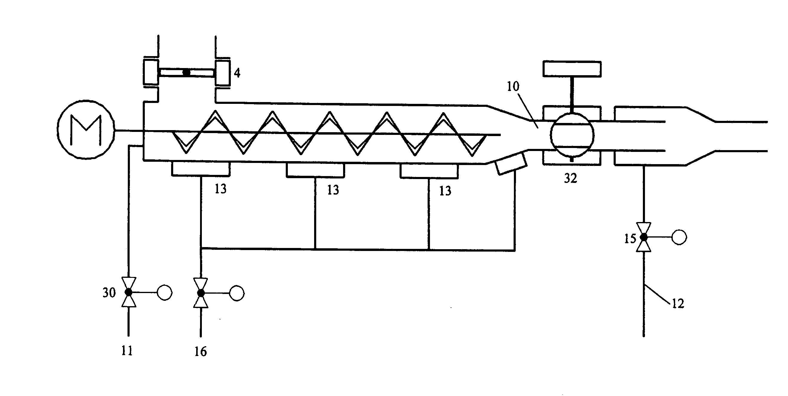
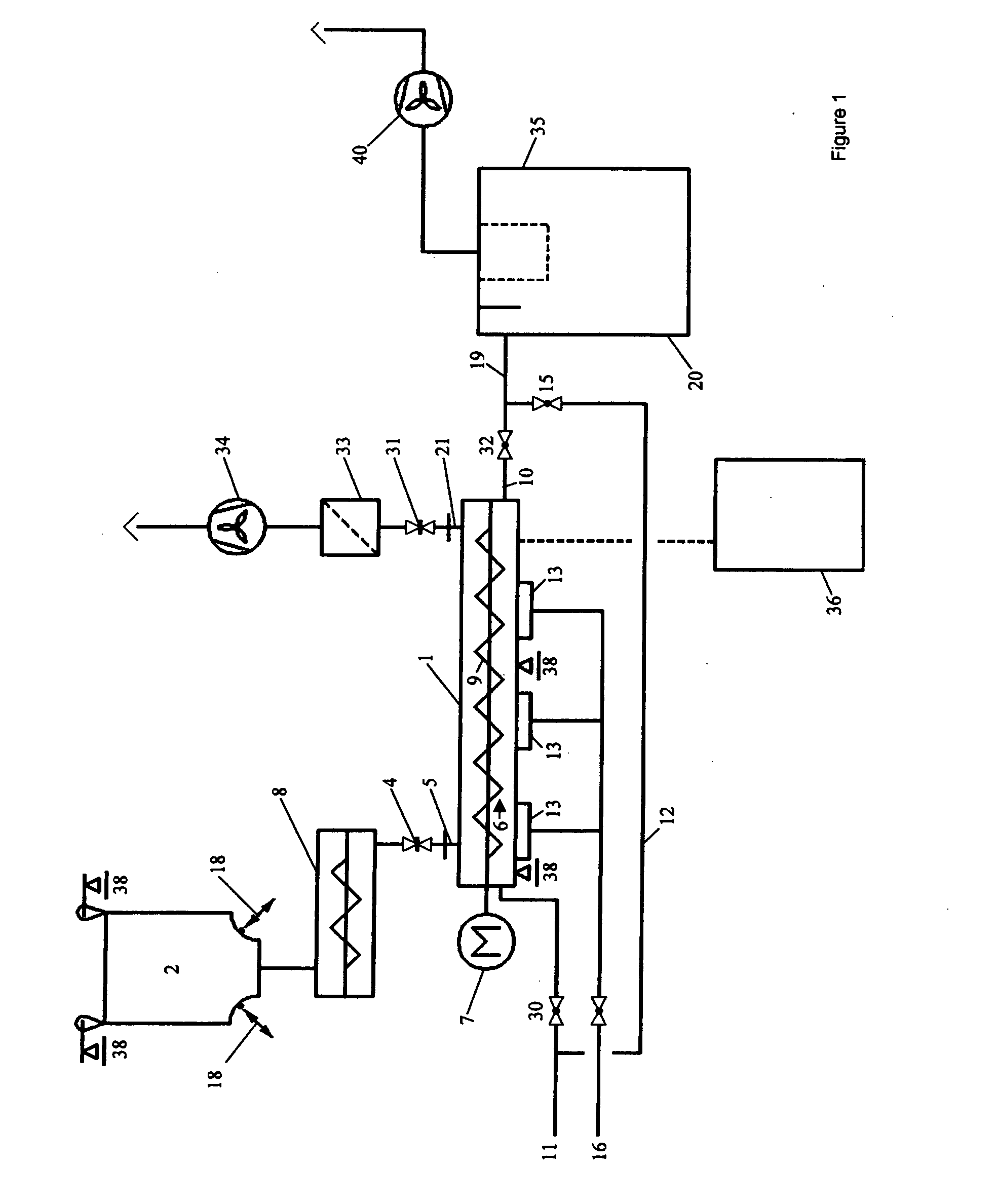
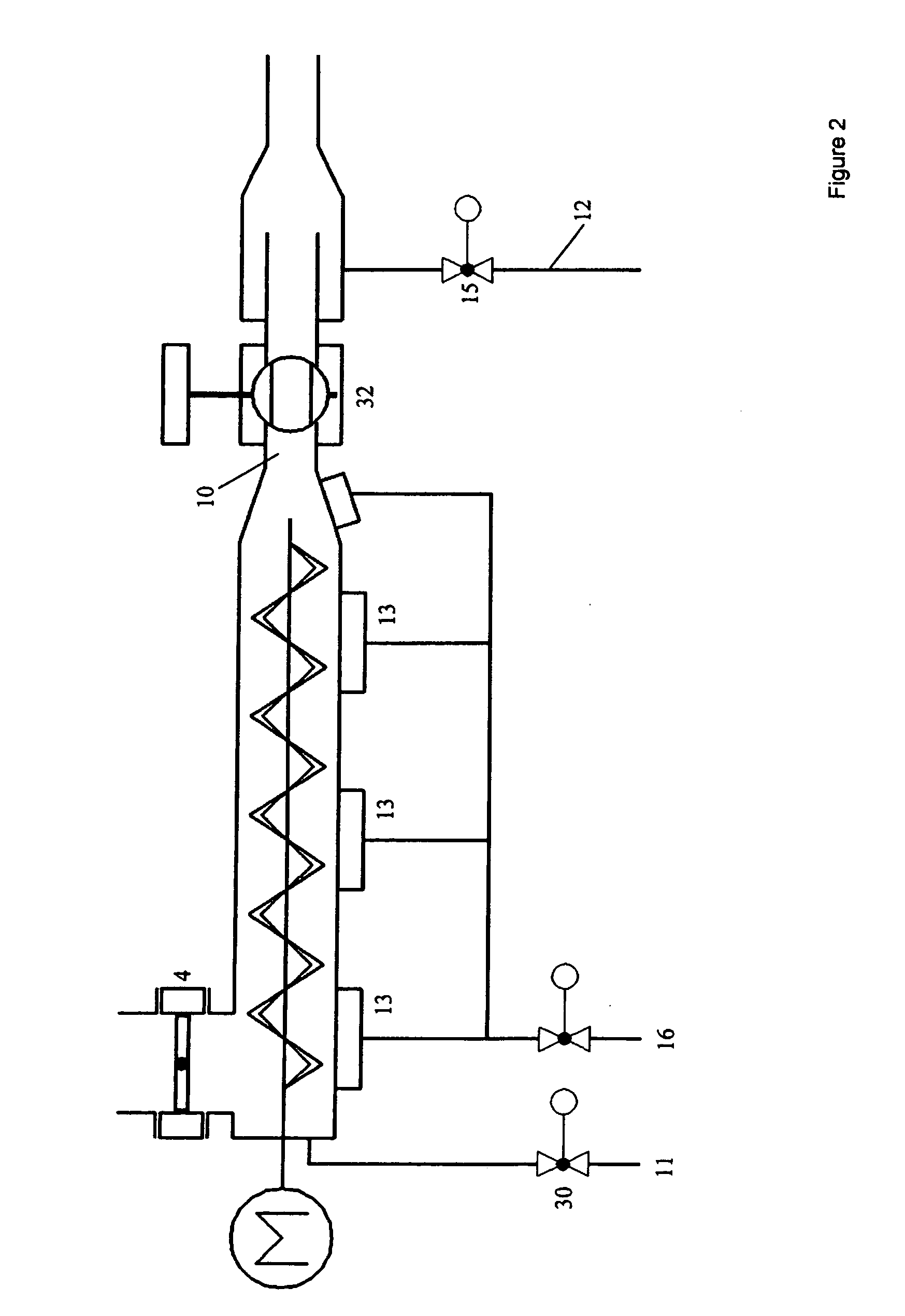
[0097] An apparatus configured in accordance with the present patent application comprised a screw barrel as longitudinal conveyor (1) which had a diameter of 200 mm and was provided with a ribbon screw having a length of 2.5 m as mechanical conveyor (9) which was installed so that it went around the wall in the longitudinal conveyor (1).

[0098] The bulk material which did not flow readily which was to be coneyed was an iron oxide having a D(v, 0.9) parameter of 4.56 μm and a density of 0.45 t / m3. The D(v, 0.9) parameter was determined by means of laser light scattering (“Mastersizer-S” instrument from Malvern Instruments) in an aqueous suspension containing 0.1% of sodium phosphate as dispersant after ultrasonic dispersion at 200 W for two minutes.

[0099] The bulk material which did not flow readily which was to be conveyed travelled into the longitudinal conveyor (1) comprising a ribbon screw from a supply container (2) via a shutoff flap (4) as input device (8). The longitudinal ...


PUM


Abstract

The invention relates to a method and an apparatus for pneumatically conveying bulk material which does not flow readily.

Description

BACKGROUND OF THE INVENTION [0001] 1. Field of the Invention [0002] The invention relates to a method and an apparatus for pneumatically conveying bulk material which does not flow readily. [0003] 2. Brief Description of the Prior Art [0004] A method of the type mentioned at the outset and an apparatus for carrying it out are known from EP 0 692 411 A1. This known technology uses a method of pneumatically conveying bulk material, in which the latter is transported in a pipe from a departure point by means of a gas stream to a reception point with the bulk material partly filling the pipe in a dense stream having a defined velocity by production of a plug in the pipe and, after closure of the inlet opening of the pipe by means of an inlet closure valve, the pipe being entirely or partly emptied by means of overpressure and with a pseudocontinuous mass flow from the departure point to the reception point being able to be established by continuous repetition of this cycle. The “pump fl...

Claims


Application Information

Patent Timeline
Patent Type & Authority Applications(United States)
IPC IPC(8): B65G53/40
CPCB65G53/08B65G53/12G01G13/026B65G53/48
Inventor KREBS, CLAUS
Owner LANXESS DEUTDCHLAND GMBH
Why Eureka
Try Eureka