Dynamic antenna allocation system

a dynamic antenna and allocation technology, applied in the field of communication systems, can solve the problems of increasing the radiated power of one radio, increasing the potential for mutual interference, and increasing the complexity of the antenna hardware design, so as to minimize the predicted interference, increase the electronic isolation, and maximize the isolation

Inactive Publication Date: 2006-07-27
SIKORSKY AIRCRAFT CORP
View PDF29 Cites 25 Cited by
  • Summary
  • Abstract
  • Description
  • Claims
  • Application Information

AI Technical Summary

Benefits of technology

[0009] When any combination of a discrete frequency, combined with an antenna located at a fixed point, and further combined with the frequency of any other module is predicted to result in an interference by the interference matrix, then the system will alert the operators and / or will automatically reassign a module / antenna for that discrete frequency to another module / antenna whose antenna is located in another fixed location which provides increased electronic isolation and minimizes the predicted interference.
[0010] The system solution according to the present invention provides modules with dedicated antennas which, when allocated optimally by the software logic, maximize isolation between modules and controls the flexible reassignment of module / antenna combinations rather than utilizing additional antennas per vehicle with selective antenna transmission line switching.
[0011] The present invention therefore results in a communication system which provides desired spatial coverage while minimizing interference caused by the practical limitations associated with the space available to locate a multiple of antennas.

Problems solved by technology

The result is an effective communications system that provides a desired spatial coverage, but may frequently results in some interferences due to the practical limitations of space available to locate antennas.
As receiver-transmitters have become capable of covering a wider spectrum of frequencies, the design of the antenna hardware has become more complex and more expensive.
Furthermore, as the capabilities of radios continue to increase, or as the number of radios installed on the airborne platform (eg; helicopter or fixed wing) increase, the potential for mutual interference increases.
Close spacing of dedicated antennas can result in the radiated power of one radio interfering with another radio whose antenna is in proximity to the other antenna that is transmitting.
The nature of the interference may be caused by transmit power of a level such that the receiving radio / antenna's receiver bandwidth processes the RF energy at the edges of its receiver bandwidth.
This undesired interference problem is further increased when the radios are wideband units that cover a broad portion of the RF spectrum.
When wideband transmitters of any kind are utilized such as for communications, navigation, IFF, etc., the harmonic content of each transmitter may also interfere with any of the receiving devices located in proximity.
The ability to locate an antenna at any arbitrary location to avoid interference may not be possible due to lack of ground plane, interference with maintenance access, or ground clearance.
As the number of antennas increases, so does the difficulty in locating antennas.

Method used


Image

  • Dynamic antenna allocation system
  • Dynamic antenna allocation system
  • Dynamic antenna allocation system

Examples


Embodiment Construction

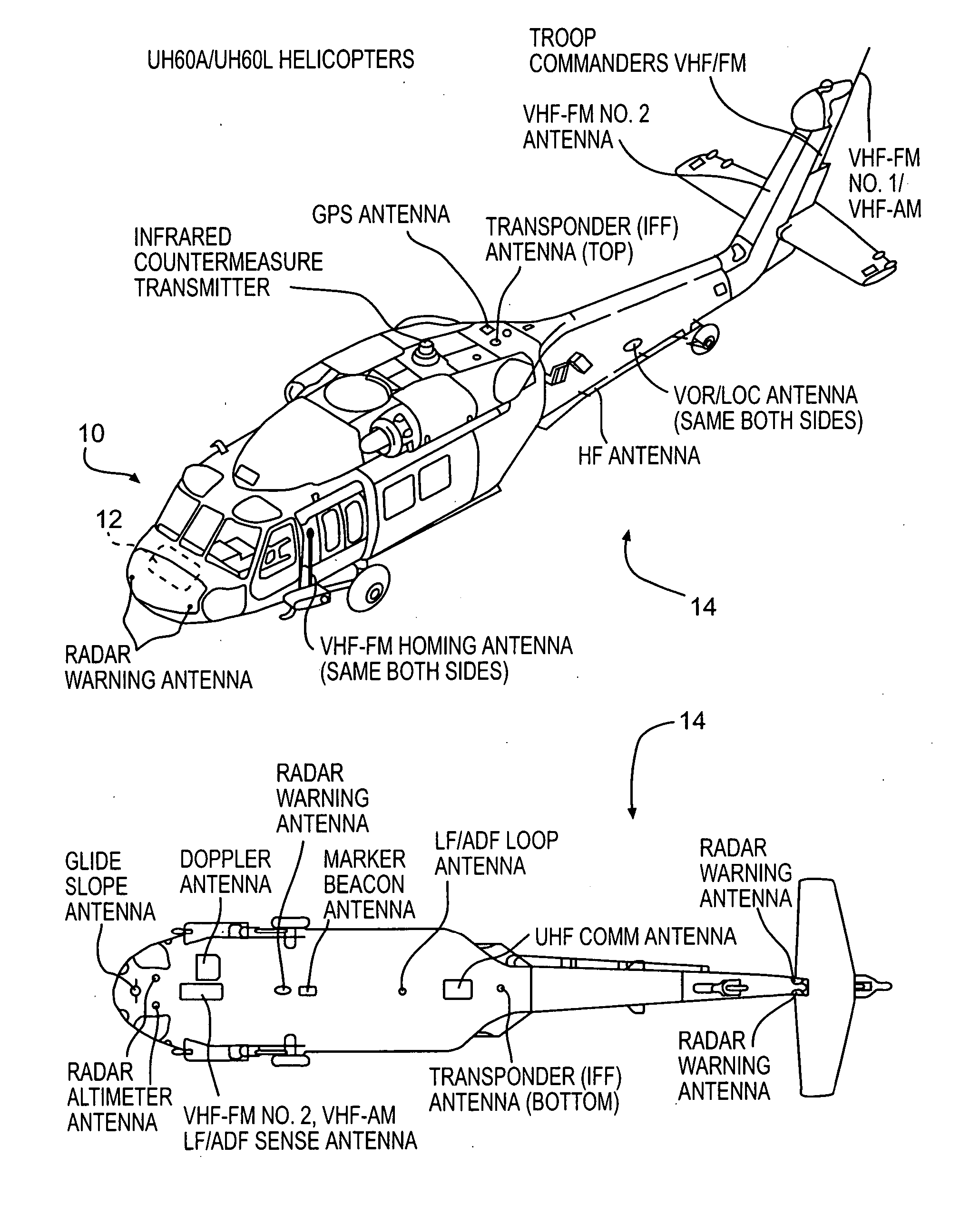
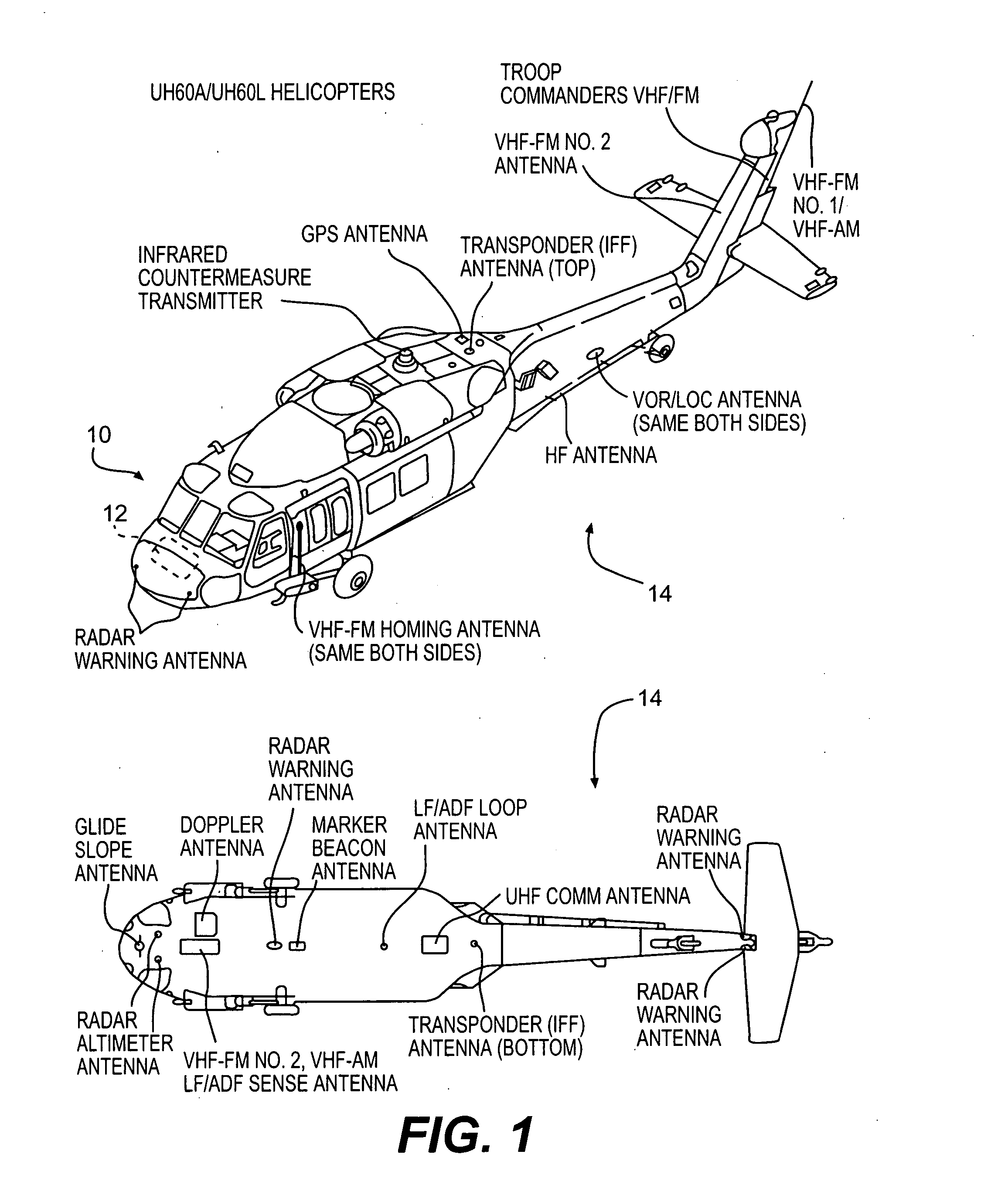
[0016]FIG. 1 illustrates a general perspective view of an aircraft 10 having a communication system 12 with an antenna array 14. Although the present invention is described hereinbelow in terms of a particular aircraft configuration as illustrated in the disclosed embodiment, it should be understood that the present invention may be modified for use with other aircraft and ground systems and sites. It should be understood that the “communication system” as used herein includes other navigation, identification, alert systems and the like which have an antenna within the antenna array 14 (FIG. 1). Such other systems will also benefit from the present invention.

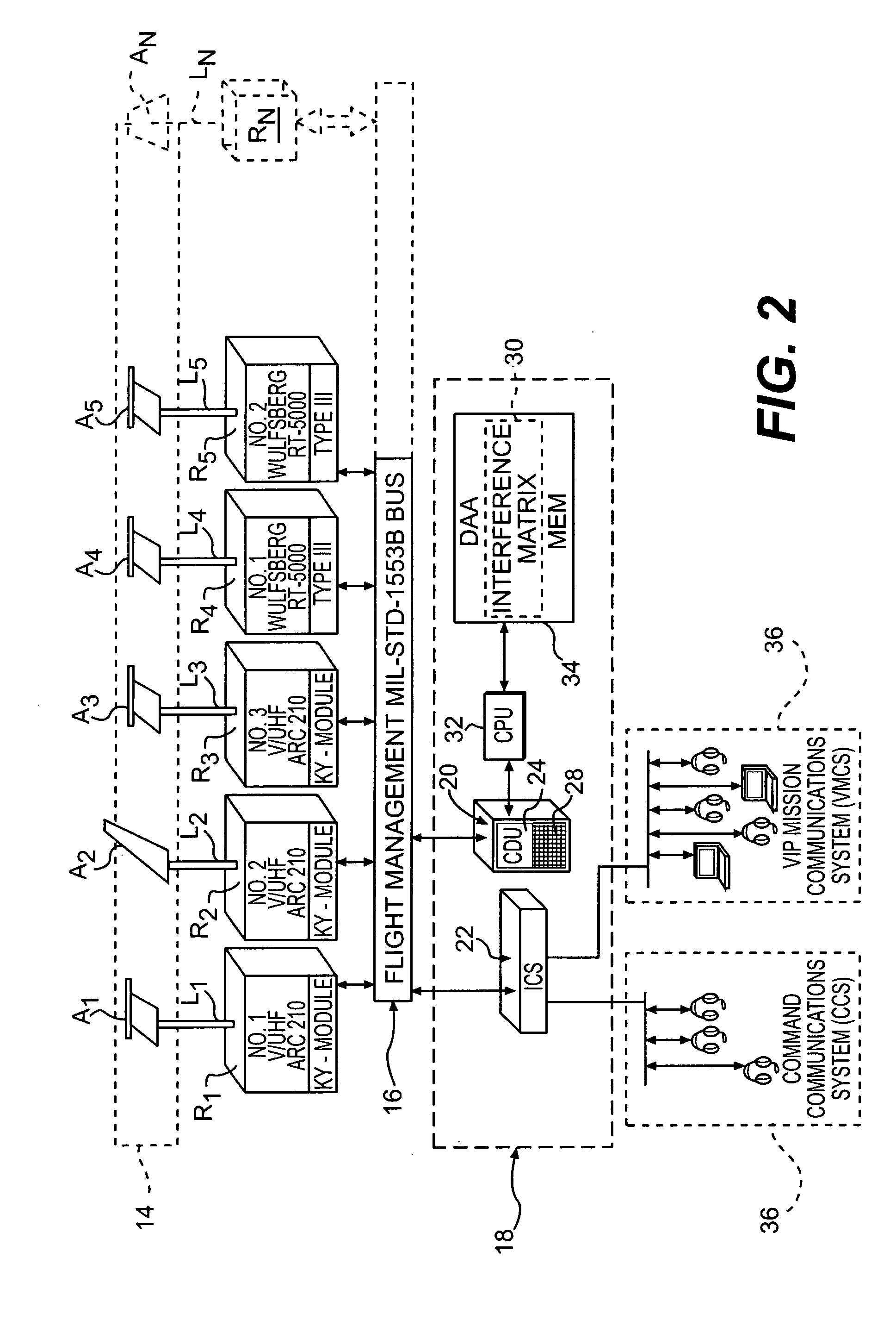
[0017] Referring to FIG. 2, the antenna array 14 includes a multiple of antennas A1-An each located in a particular location on the aircraft 10 (FIG. 1). Due to the fixed location, each antenna A1-An may also be subject to interference from, and subject other antennas, to interference. Each antenna A1-An provides dedicated tran...


PUM


Abstract

A communication system which manages an antenna array by a software-implemented control system that has prior knowledge of the potential interactions among Communications / Navigation and Identification modules. When any transmission / reception combination from a particular antenna is predicted to result in interference with another particular antenna by the interference matrix, then the system will alert the operators and / or will automatically reassign a module / antenna combination to provide increased electronic isolation and minimize the predicted interference. This system solution provides dedicated antennas which maximizes isolation between systems and emphasizing flexible reassignment of hardware rather than additional antenna complexity and / or selective antenna RF transmission line switching.

Description

BACKGROUND OF THE INVENTION [0001] The present invention relates to a communication system, and more particularly to management of an antenna array. [0002] Aircraft communications systems usually include a receiver-transmitter, a digital interface of the control panel mechanism to and from the receiver transmitter, and an antenna system. The antenna system of a typical communications system is connected to the receiver-transmitter by a coaxial cable, sometimes known as a transmission line. This basic arrangement can be found in aircraft and in ground installations. [0003] Some conventional communications systems connect the receiver-transmitter and the antenna as a dedicated, matched pair, and the antenna is tuned to operate efficiently over the particular receiver-transmitter's operating range. In more complex applications, a receiver-transmitter may be connected to a second antenna by a control mechanism and a coaxial relay. A typical application may be an upper antenna and a lowe...

Claims


Application Information

Patent Timeline
Patent Type & Authority Applications(United States)
IPC IPC(8): H04B1/02
CPCH01Q1/28H01Q1/521H04B1/10
Inventor ANTTILA, DONALD S.
Owner SIKORSKY AIRCRAFT CORP
Why Eureka
Try Eureka