
Method and apparatus for position sensing

a position sensing and position technology, applied in direction finders using radio waves, instruments, multiplex communication, etc., can solve the problems of limited interest in wireless interfaces, device use is rather awkward, and the general range of operation of technologies is limited

Inactive Publication Date: 2006-07-27
XYZ INTERACTIVE TECH
View PDF7 Cites 184 Cited by
  • Summary
  • Abstract
  • Description
  • Claims
  • Application Information

AI Technical Summary

Benefits of technology

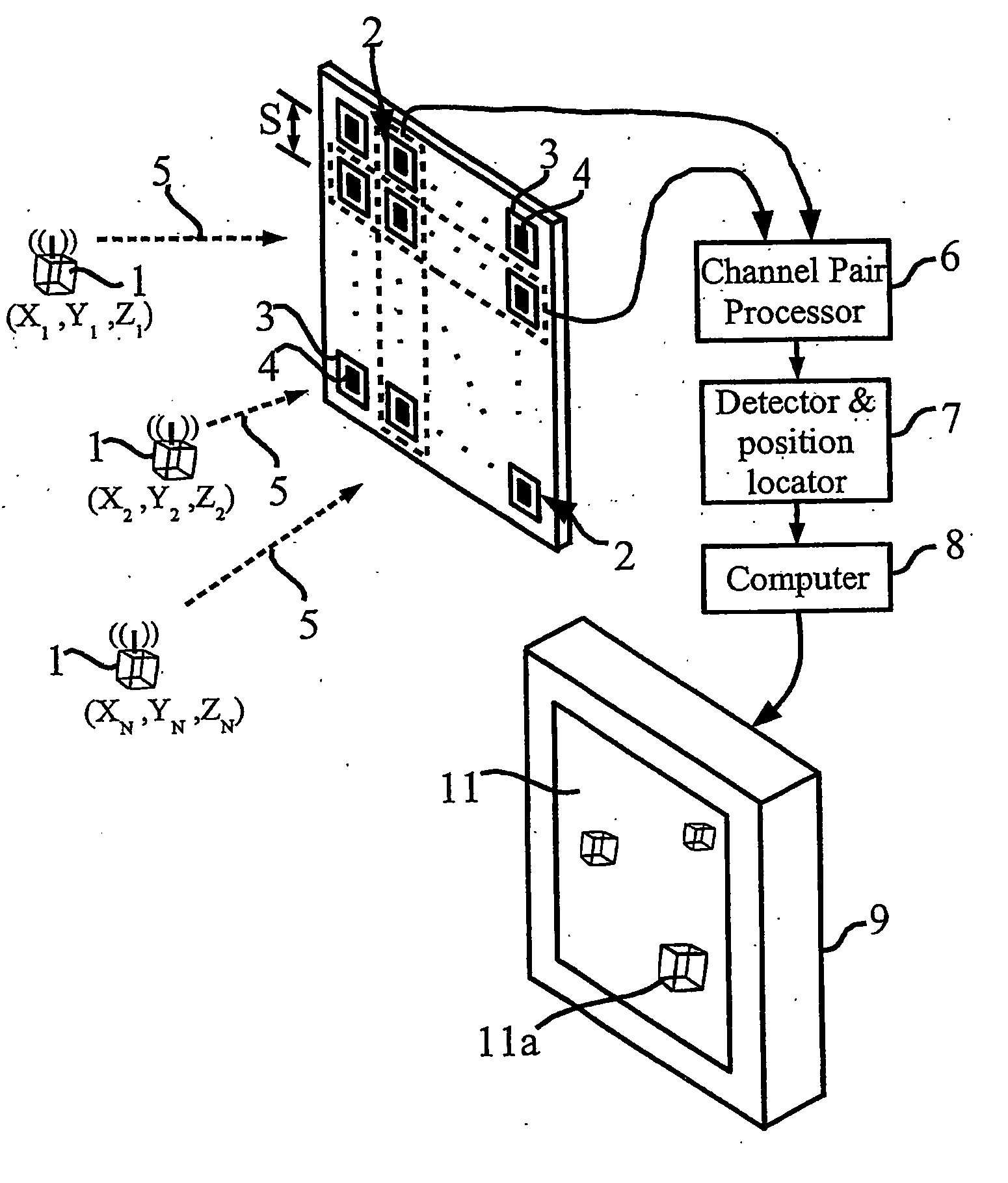
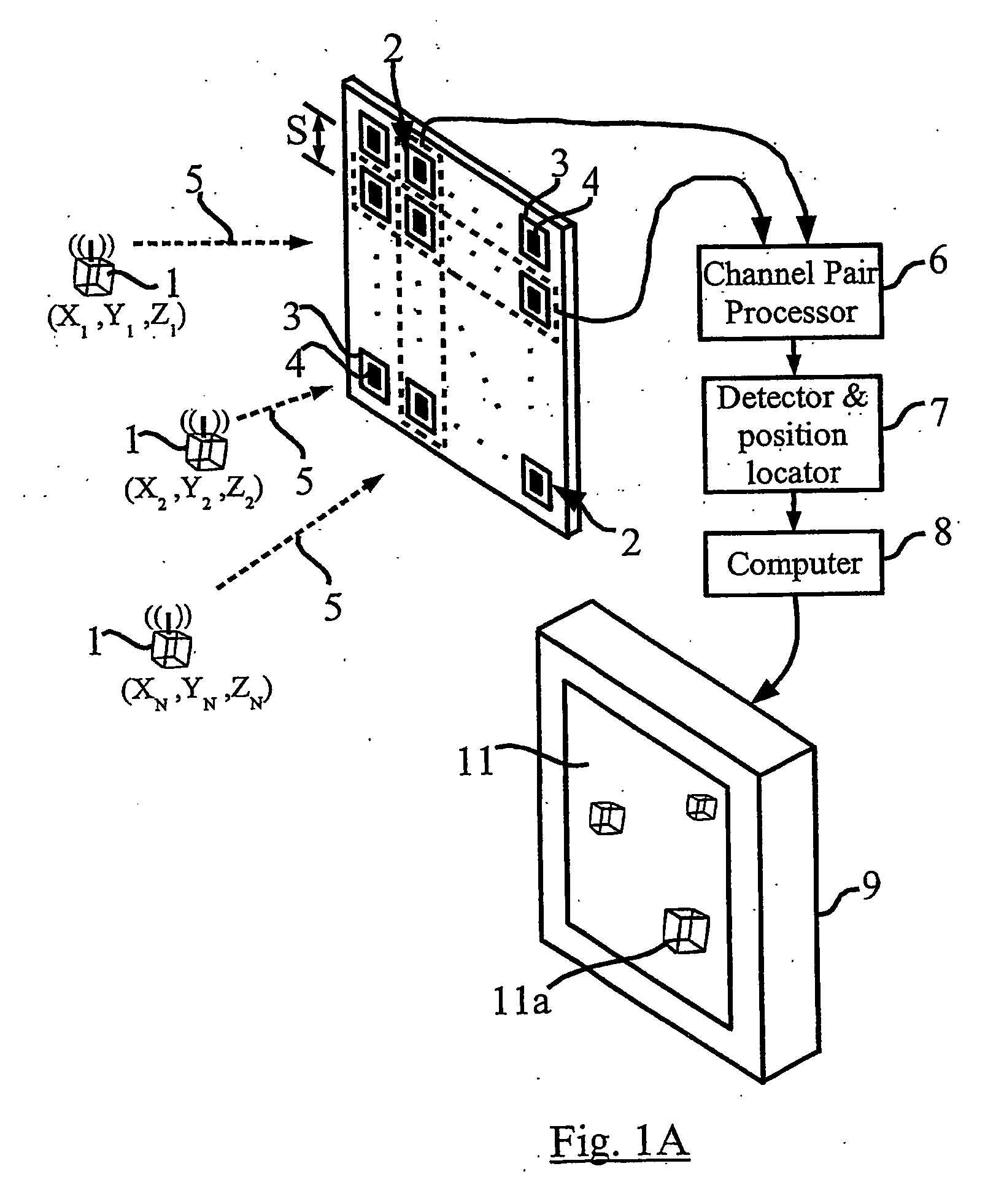
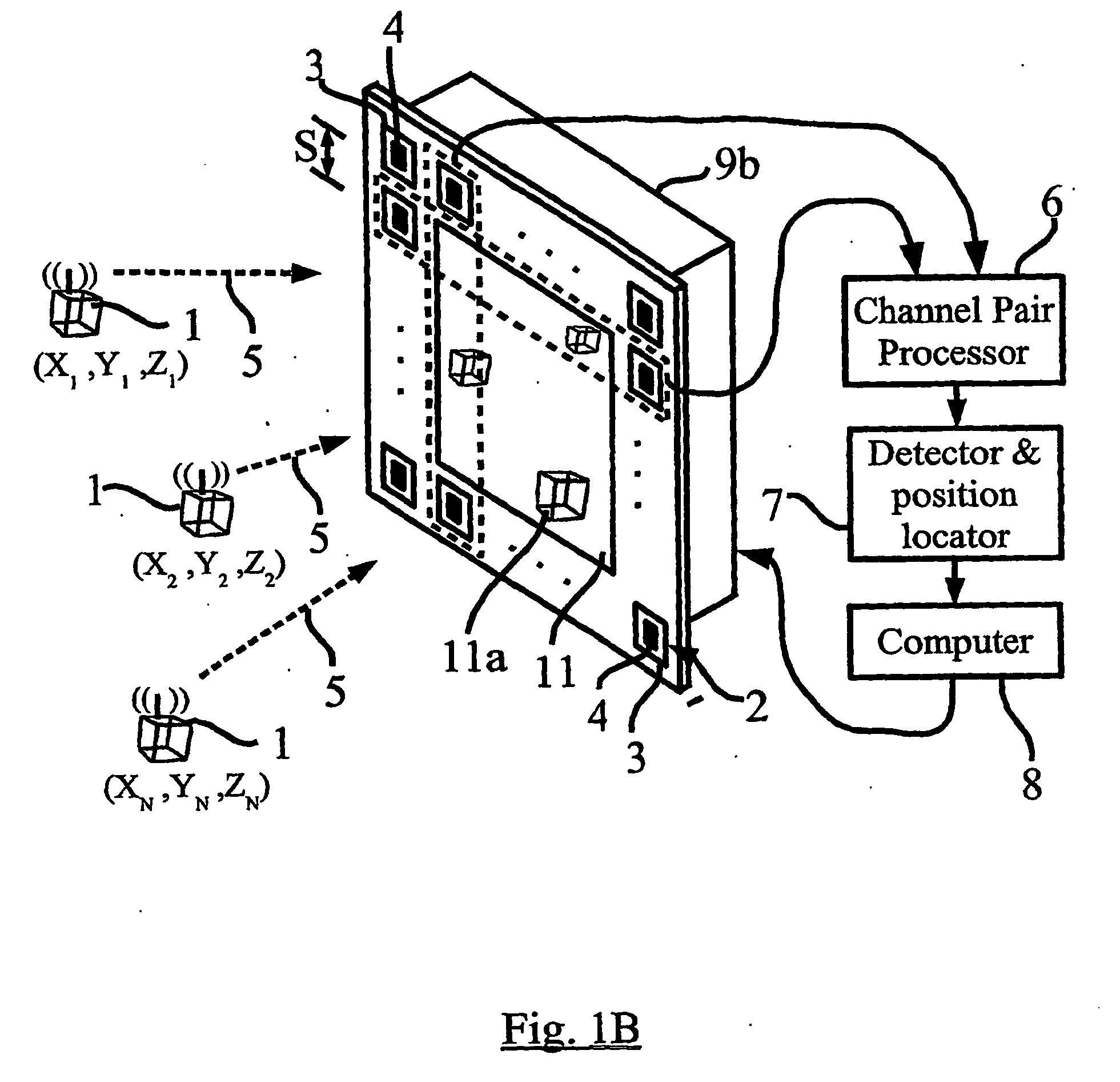
[0018] An aspect of the present invention relates to a wireless position sensing computer input device that is responsive to one or more electromagnetic transmitting devices that are physically moved in three-dimensional space. The receiver is a passive array and can process signals from multiple transmitting devices that use unique DSSS, FHSS, and THSS spread-spectrum methods with pseudo-noise (PN) modulating codes. A single receiver can simultaneously detect and position multiple transmitters allowing combinations of three-dimensional position and angle orientation measurement of devices containing multiple transmitters.

Problems solved by technology

Although the concept behind wireless interfaces was known prior to this date, interest in wireless interfaces was limited until the release of the 2.4 GHz unlicensed band for industrial, scientific and medical (ISM) applications.
These technologies generally have limited range of operation and commonly require that a power cable be tethered to the hand-held device to provide power and be operable to switch signals between the handheld device and a base receiver.
Accordingly, these devices are rather awkward to use as they are not fully wireless.
Techniques of this kind are impractical at close range because time delays are too short to be measured reliably and accurately.
However, UWB technologies employ a wideband that limits the practical ability of detecting and locating UWB transmitters in short range.
Existing systems that display absolute or relative position introduce some kind of mechanical or data-link delay that lowers the presentation speed to any display or monitoring device.

Method used


Image

  • Method and apparatus for position sensing
  • Method and apparatus for position sensing
  • Method and apparatus for position sensing

Examples


Embodiment Construction

[0058] Before discussing embodiments of the invention in detail, it is useful to review certain technological principles used to implement certain features of the present invention in order to provide context in understanding certain implementations and features of the present invention.

Spread Spectrum Signals

[0059] Spread-spectrum signaling can be effected in a number of ways. Examples of spread-spectrum signals include Direct Sequence Spread Spectrum (DSSS) signals, Frequency Hopping Spread Spectrum (FHSS) signals, Time Hopping Spread Spectrum (THSS) signals, Linear Frequency Sweeping (Chirp) signals, Hybrid signals, and the like. Wireless products frequently employ some type of spread spectrum technique, such as direct sequence spread spectrum (DSSS) or frequency hopping spread spectrum (FHSS), to communicate between the transmitter and receiver (single or two-way). A distinguishing feature of the spread spectrum technique is that the modulated output signals occupy a much gre...


PUM


Abstract

Embodiments of the present invention include one or more wireless transmitting devices and an array of receiver units for receiving wireless communications from the transmitting devices. The transmitter devices and receiver units can be arranged in one, two or three dimensional configurations. Signals are transmitted from the devices for identification and accurate location determination. Spread spectrum techniques can be used, such as DSSS, FHSS, THSS, and pseudo-noise (PN) coding schemes, or combinations thereof. The transmitting devices can generate one or a plurality of data signals that are orthogonal-code modulated, to be decoded by the receiver units and a processor associated therewith. A plurality of transmitter signals can be received, identified, located, and data demodulated substantially simultaneously using embodiments of the invention. The combined use of array processing methods and diversity schemes can be used to reduce the effects of signal multi-path and occlusion.

Description

PRIORITY CLAIM [0001] The present application claims priority from Canadian patent application number CA 2,397,431, filed Aug. 9, 2002, the contents of which ate incorporated herein by reference. FIELD OF INVENTION [0002] The present invention relates generally to computing interface devices and more particularly relates to a method and apparatus for position sensing. BACKGROUND OF INVENTION [0003] Computer systems configured with human interface devices are common for and are popular in a wide variety of business and educational applications. The most common interface device is the mouse and keyboard, which in their traditional format are coupled to the computer by a hard-wired connection. Since about 1990, wireless interface devices have become more common in the marketplace. Although the concept behind wireless interfaces was known prior to this date, interest in wireless interfaces was limited until the release of the 2.4 GHz unlicensed band for industrial, scientific and medica...

Claims


Application Information

Patent Timeline
IPC IPC(8): H04Q7/20G01S1/68G01S5/02G06F3/0346G06F3/038H04B1/69H04B1/707H04B1/713H04B7/005H04J13/00
CPCG01S5/02H04B1/69H04B2201/70715H04J13/004G01S5/0295
Inventor LOHBIHLER, ANDREW
Owner XYZ INTERACTIVE TECH
Learn More