
Implantable prosthetic device for connection to a fluid flow pathway of a patient

Inactive Publication Date: 2006-07-27
TECH ADVANCEMENT GROUP
View PDF14 Cites 59 Cited by
  • Summary
  • Abstract
  • Description
  • Claims
  • Application Information

AI Technical Summary

Benefits of technology

[0010] It is an object of the present invention to provide a device which decreases the instances of stroke, embolism, and other potentially harmful effects associated with the presence of foreign particles within the fluid flow pathway of a patient.
[0011] It is another object of the invention provide an implantable prosthetic device for connection to the fluid flow pathway of a patient that helps to maintain long-term adequate flow of fluids through fluid flow pathways by filtering foreign particles and providing a means for monitoring the blood flow through the device.

Problems solved by technology

A concern commonly encountered in all these techniques is the accidental release of portions of the clots, plague, thrombus, debris, gas bubbles, or other embolic particulates, resulting in emboli which can lodge elsewhere in the vascular system.
Such emboli may be extremely dangerous to the patient, and may result in myocardial infarction, stroke, or limb ischemia.
However, since this device consists of a single filter, it does not provide for an alternative fluid flow path in the event that the filter becomes clogged.
This device, however, is designed only to capture embolic particles dislodged during the course of medical procedures and cannot be surgically implanted into a fluid flow pathway for long-term protection against naturally occurring emobolic particles.
This device does not provide a means by which embolic particles are filtered within the fluid flow pathway, and thus, does not serve to decrease a patient's risk of stroke, pulmonary embolism or other potentially deadly medical condition.
The tube structures of this device, however, do not comprise filtering devices for capturing hazardous embolic particles within a patient's fluid flow pathway.
Obviously, there are still major disadvantages associated with the existing technology which must be overcome.
Specifically, the present day technology fails to provide patients with long-term protection against the potentially fatal conditions that result from blocked fluid flow pathways, including stroke, pulmonary embolism, and ischemia.
Until now, there have been no implantable prosthetic devices containing multiple fluid flow pathways and filtering mechanisms to ensure the adequacy of the fluid flow within a patient capable of overcoming this technological shortfall.

Method used


Image

  • Implantable prosthetic device for connection to a fluid flow pathway of a patient
  • Implantable prosthetic device for connection to a fluid flow pathway of a patient
  • Implantable prosthetic device for connection to a fluid flow pathway of a patient

Examples


Embodiment Construction

[0023] Strokes result from a sudden loss of brain function caused by a blockage or rupture of a blood vessel to the brain and is often characterized by loss of muscular control, diminution or loss of sensation or consciousness, dizziness, slurred speech, or other symptoms that vary with the extent and severity of the damage to the brain. The implantable prosthetic device, the preferred embodiments of which are herein disclosed and described is designed to decrease the instances of strokes, and other embolic events, such as pulmonary embolisms and ischemia in a patient by providing multiple pathway for the flow of fluids within a patient and a non-invasive method of monitoring the continued proper function of the device.

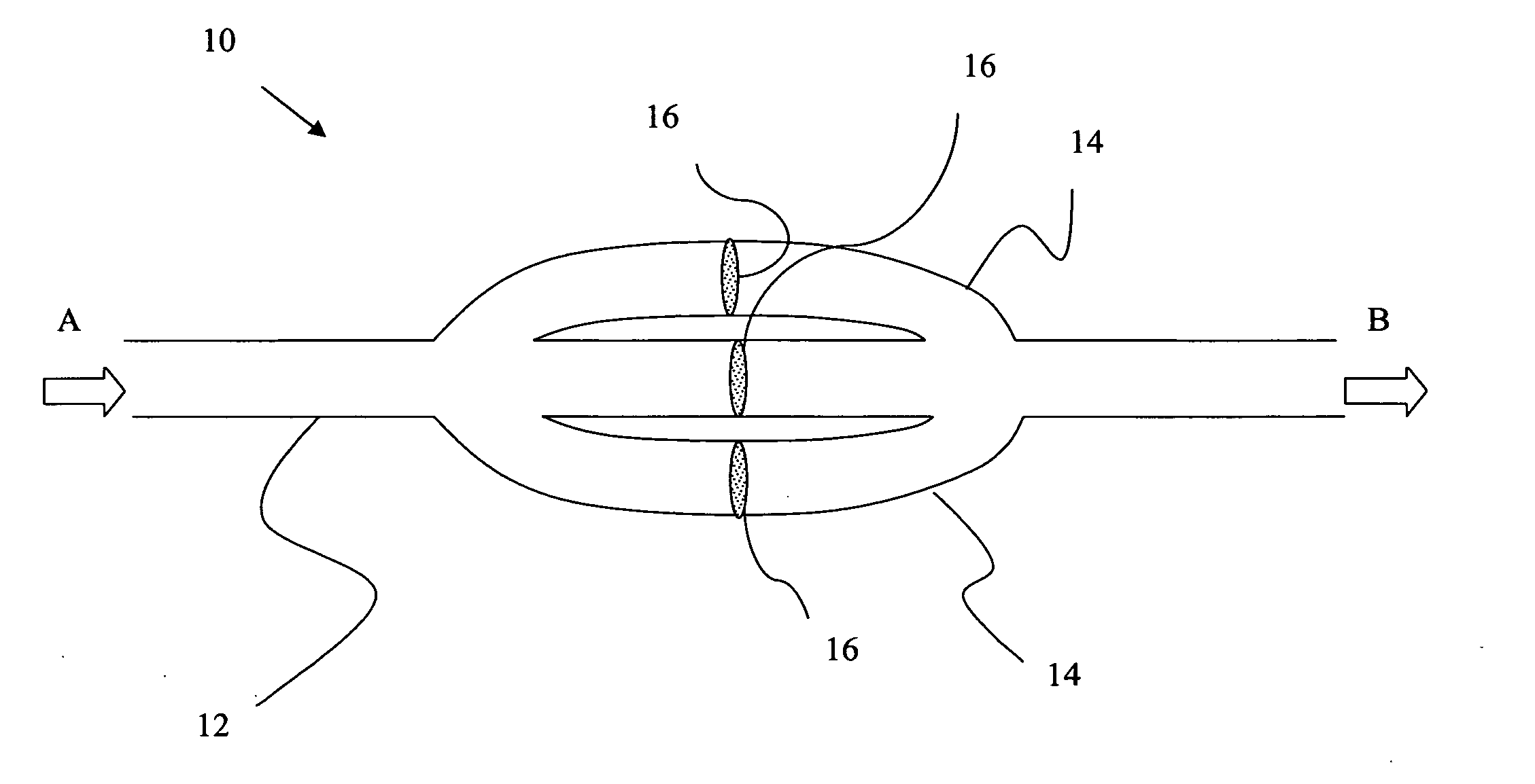
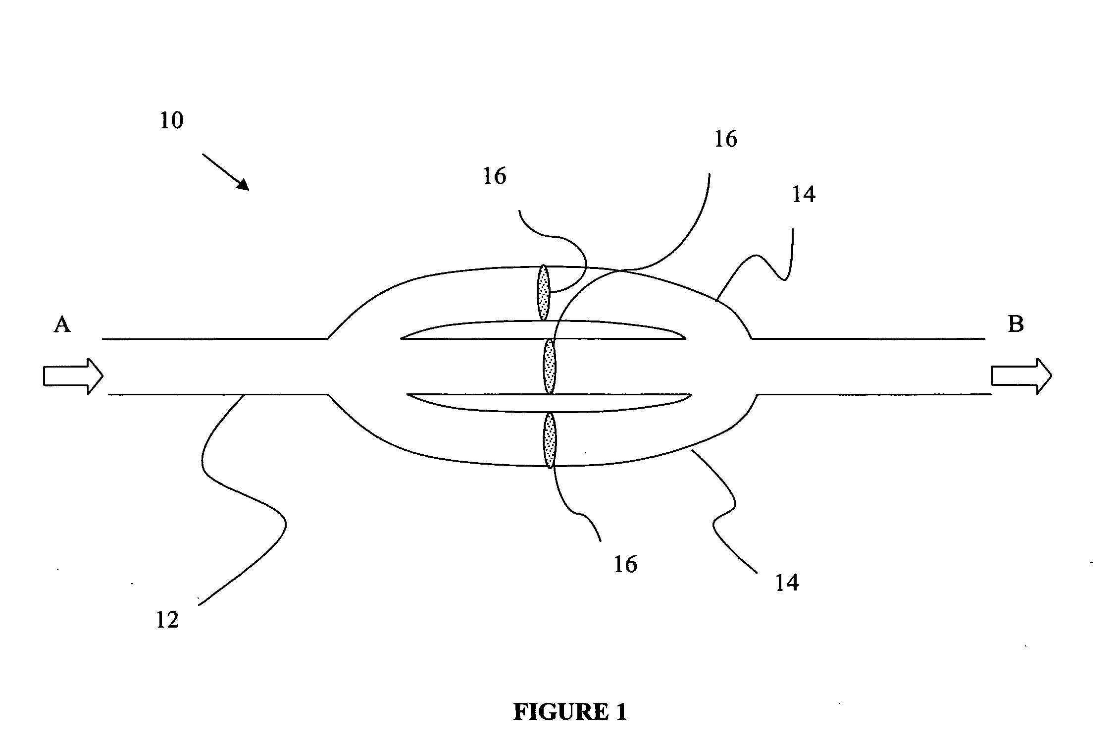
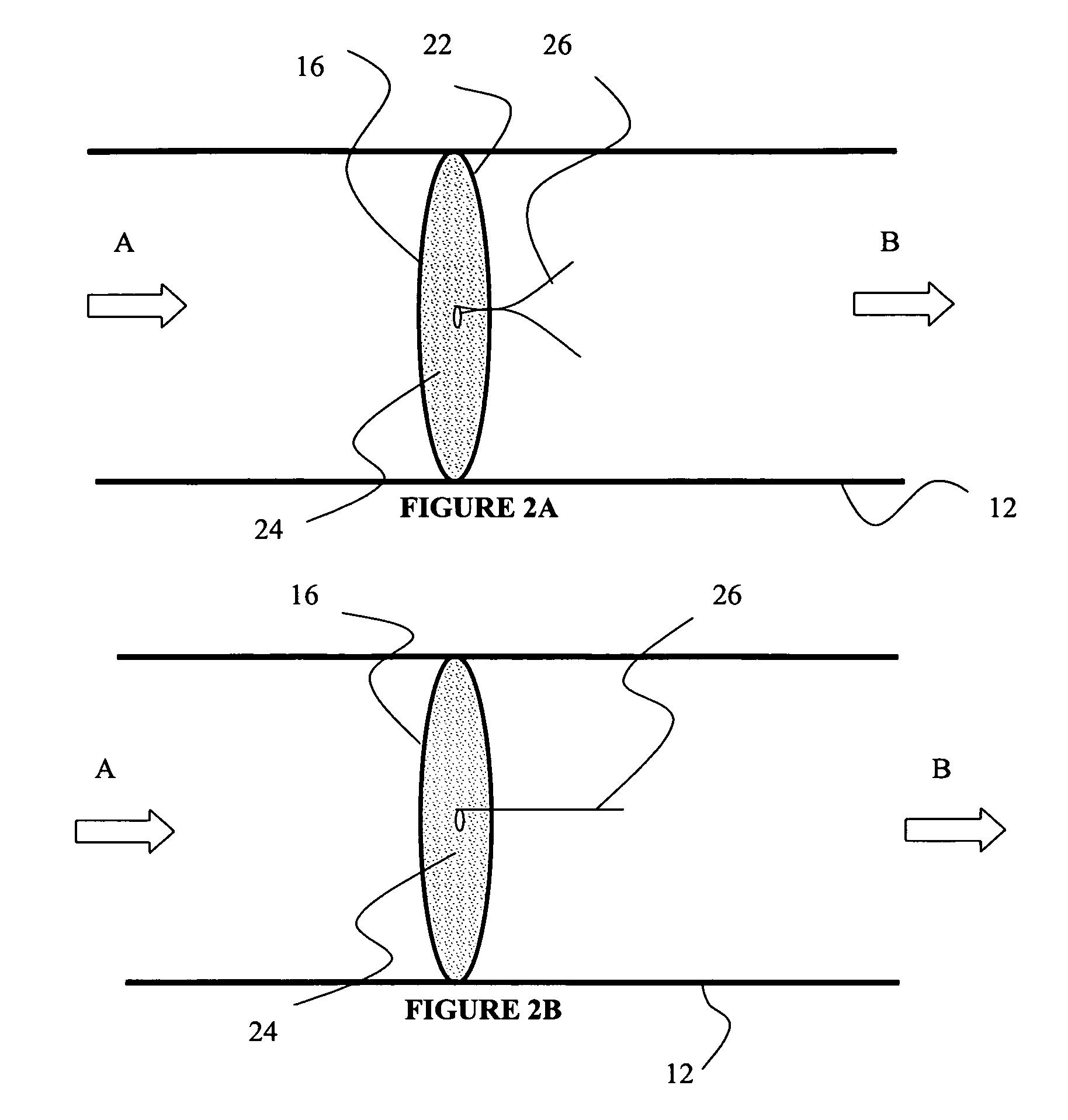
[0024] In a first embodiment, an implantable vascular prosthesis for connection to the vascular pathway of a patient is provided as depicted in FIG. 1. Vascular prosthesis 10 includes a primary tube structure 12 defined by a proximal end A, a distal end B and a wall ...


PUM


Abstract

An implantable prosthetic for connection to a fluid flow pathway of a patient. The prosthetic is comprised of a primary tube structure which is in communication with a plurality of secondary tube structures each of which contains filters for trapping embolic particles, such as blood clots, air bubbles, thrombus. etc. within a fluid flow pathway within a patient. The prosthetic also contains a monitoring device to non-invasively the flow of fluids through a patient's fluid flow pathway.

Description

BACKGROUND OF THE INVENTION [0001] 1. Field of the Invention [0002] This invention relates to a implantable prosthetic device for connection to the fluid flow pathway of a patient, and more particularly to a implantable prosthetic device containing a plurality of tube structures having a filter for trapping objects such as embolic particles. [0003] 2. Discussion of Related Art [0004] Increasing numbers and types of intralumenal procedures are being performed on medical patients. For example, there are intravascular blood flow measurement procedures, intravascular atherectomy procedures, intravascular drug therapy procedures, balloon angioplasty procedures, intravascular stent installation procedures, and even intravascular coronary bypass procedures (see, for example, U.S. Pat. No. 5,976,178 to Goldsteen, et al. which is herein incorporated by reference in its entirety). A concern commonly encountered in all these techniques is the accidental release of portions of the clots, plague...

Claims


Application Information

Patent Timeline
IPC IPC(8): A61F2/01A61F2/06
CPCA61F2/01A61F2002/018A61B5/4851A61F2/82A61F2/06A61F2230/0006A61B19/46A61B90/06
Inventor MCEWAN, JOHN ARTHUR
Owner TECH ADVANCEMENT GROUP
Learn More