Cutting device for thin metallic plate

a cutting device and metallic plate technology, applied in the direction of turning machine accessories, manufacturing tools, tube shearing machines, etc., can solve the problems of reducing the durability of the blade, the edge of the cutter becomes too sharp, and the inner wall of the groove is blurred, so as to achieve the effect of positive formation of metal rings, insufficient constriction, and increased contact time of the cutter

Inactive Publication Date: 2006-08-03
HONDA MOTOR CO LTD
View PDF10 Cites 4 Cited by
  • Summary
  • Abstract
  • Description
  • Claims
  • Application Information

AI Technical Summary

Benefits of technology

[0024] Based on the tests, the inventor found that the shape of the cut edge changes according to a depth of the shearing cutter in the groove during the cutting of the drum. When a distance between the edge of the shearing cutter and the deepest portion of the groove is smaller than 0.2 times the thickness of the drum, it takes a long time for the cutter to completely withdraw from the groove after cutting, thereby increasing contact time of the cutter and the cut edge on the fixed side of the drum. Thus, the cut edge formed on the unfixed side of the drum and the cut edge formed on the fixed side of the drum become different in shape. Moreover, when a distance between the edge of the shearing cutter and the deepest portion of the groove is larger than 0.4 times the thickness of the drum, the depth of the shearing cutter in the groove becomes smaller and the pressing force of the drum to the inner walls of the groove is reduced, thereby insufficiently forming the constriction. For this reason, in the present invention, the edge of the shearing cutter is caused to reach a position at a distance of 0.2 to 0.4 times the thickness of the drum from the deepest portion of the groove. Thus, the difference in shape between the cut edge formed on the unfixed side of the drum and the cut edge formed on the fixed side of the drum becomes extremely small and metal rings can be positively formed by cutting.

Problems solved by technology

When the blade angle is smaller than 50°, the edge of the cutter becomes too sharp and nick or the like on the blade reduces durability.
In the case where the interval is smaller than 15 times, the thin plate is not bent gradually along the curved surfaces on the inner walls of the groove when the thin plate is pressed by the cutter, causing blurs along the inner walls of the groove after cutting.
In the case where the interval is larger than 30 times, the thin plate makes contact with the deepest portion of the groove before being cut, resulting in an insufficient constriction.

Method used


Image

  • Cutting device for thin metallic plate
  • Cutting device for thin metallic plate
  • Cutting device for thin metallic plate

Examples


Embodiment Construction

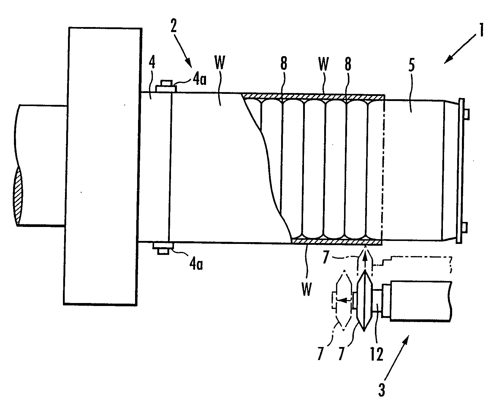
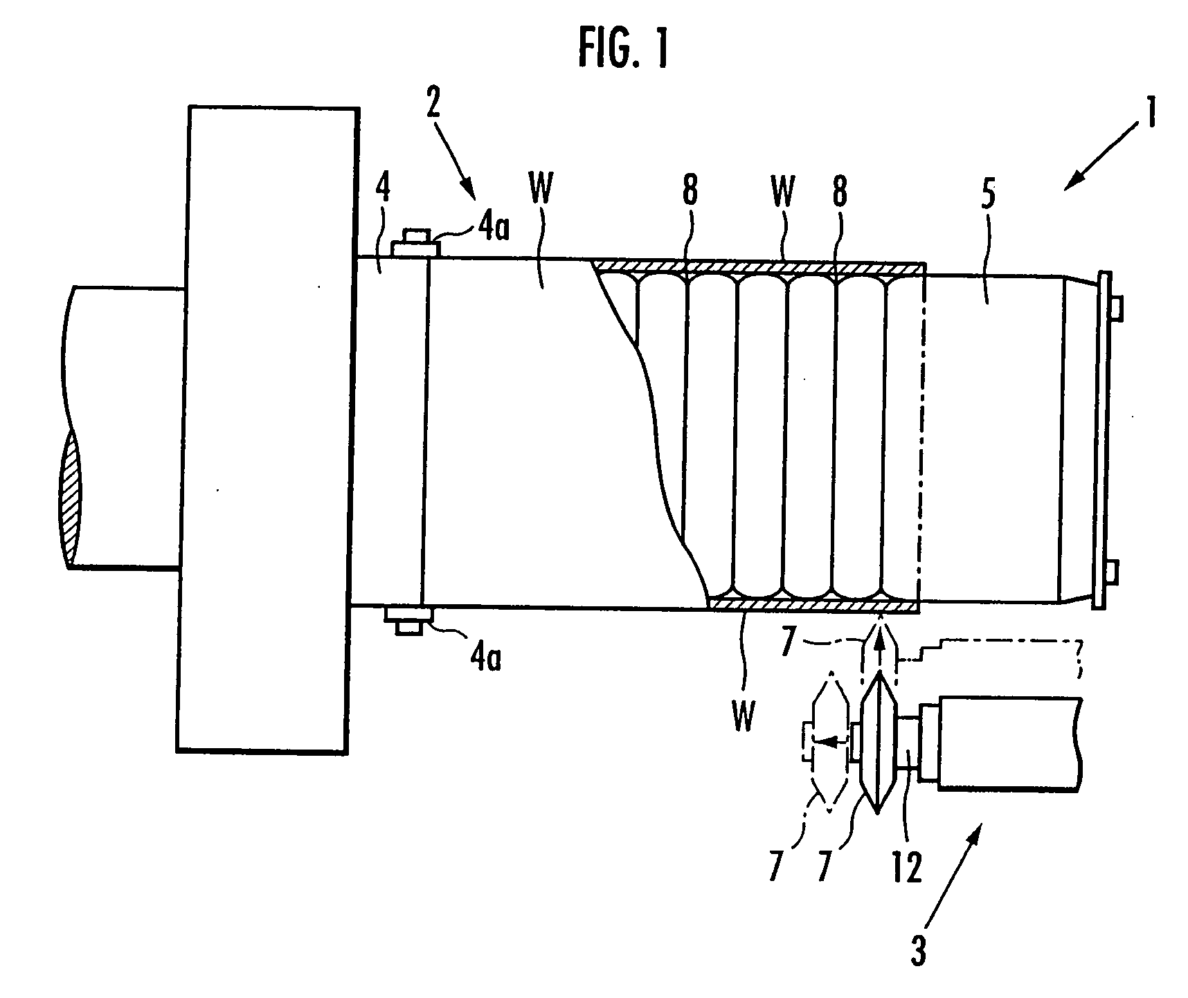
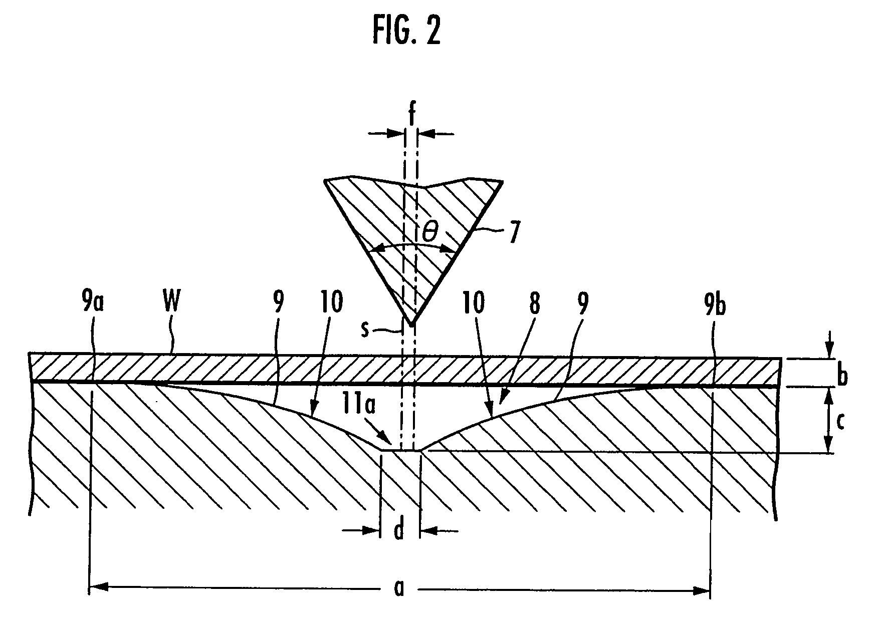
[0037] A cutting device 1 of the present embodiment shown in FIG. 1 cuts a metal drum W in round slices with a predetermined width to manufacture metal rings for a belt of an infinite variable speed drive (not shown). The drum W is formed as follows: a flat thin plate which is shaped like a rectangle and is made of a maraging steel is formed into a cylinder and then both edges of the plate are butt against each other and are subjected to weldbonding.

[0038] As shown in FIG. 1, the cutting device 1 of the present embodiment is constituted of drum holding means 2 for holding the drum W and cutting means 3 for cutting the drum W.

[0039] The drum holding means 2 comprises a support shaft 4 which is rotated by rotary driving means (not shown) and a holder 5 which is connected to the support shaft 4, holds the drum W on the outer periphery of the holder 5, and serves as a contacting member making contact with the inner surface of the drum W.

[0040] As shown in FIG. 1, the holder 5 is made...


PUM

PropertyMeasurementUnit
blade angleaaaaaaaaaa

Abstract

A cutting device for a thin metallic plate is provided which shortens time for shaping or the like on a cut edge to improve manufacturing efficiency, and increases the life of a cutter. The cutting device for cutting a thin metallic plate W with a predetermined width includes a shearing cutter 7 which is made of a metal having a higher hardness than the thin plate W and has a blade angle of 50 to 90°. A contacting member 5 is provided which includes a groove 8 facing the shearing cutter 7 and makes contact with the back side of the thin plate W. In the groove 8, an interval a between upper edges 9a and 9b of inner walls 9 is set at 15 to 30 times a thickness b of the thin plate W. A depth c of a deepest portion 11 in the groove 8 is set at one to three times the thickness b of the thin plate W. The inner walls 9 of the groove 8 include curved surfaces 10, each of which has a curvature radius of 15 to 50 times the thickness b of the thin plate.

Description

TECHNICAL FIELD [0001] The present invention relates to a cutting device for cutting a thin metallic plate and particularly concerns a cutting device suitable for cutting in round slices a cylindrical drum formed of a thin metallic plate to form a plurality of metal rings. BACKGROUND ART [0002] For example, regarding belts used for power transmission in infinite variable speed drives, a laminated ring formed by stacking a plurality of metal rings is used to combine a plurality of elements arranged in a laminated construction like a ring. The metal rings constituting such a laminated ring are formed by cutting a cylindrical drum, which has been formed by performing weldbonding on both ends of a rectangular thin metallic plate, in round slices with a predetermined width. [0003] Conventionally the following method is known: when the cylindrical drum is cut with a predetermined width to form the metal rings, one end of the drum is supported by clamping, a rotating grindstone is pressed ...

Claims


Application Information

Patent Timeline
Patent Type & Authority Applications(United States)
IPC IPC(8): B26D7/14B23D21/00B23D21/04B23D35/00B26D1/00B26D3/16
CPCB23D21/00Y10T82/16803Y10T82/16967B23D35/001Y10T83/343
Inventor MINOWA, YOSHIYUKIHAGA, FUMITAKAYOSHIMURA, TAKESHINAGAO, YUICHIFUJIYAMA, TAKEYUKINAKAMURA, TARO
Owner HONDA MOTOR CO LTD
Why Eureka
Try Eureka