
Remote operation wire line core sampling device

a sampling device and wire line technology, applied in the direction of drilling pipes, drilling rods, borehole/well accessories, etc., can solve the problems of inability to take samples, inability to effect sampling, and substantially reduced capacity, so as to improve the quality of core samples and improve operational efficiency

Inactive Publication Date: 2006-08-03
MITSUI ENG & SHIPBUILD CO LTD +2
View PDF3 Cites 20 Cited by
  • Summary
  • Abstract
  • Description
  • Claims
  • Application Information

AI Technical Summary

Benefits of technology

[0012] It is an object of the present invention to modify a conventional sea-bottom core drill as described above and an instrument for wire line core sampling conducted on the ground, and to apply the wire line system to a stabilized sea-bottom core drill for use at the sea bottom, thereby achieving an improvement in terms of operational efficiency and an improvement in core sample quality through hole wall preservation.
[0017] According to the present invention, a stabilized sea-bottom core drill is used, and an instrument for wire line core sampling conducted on the ground is modified such that the wire line system can be adopted for sea-bottom use, thereby achieving an improvement in terms of operational efficiency and hole wall preservation.
[0018] It is an object of the present invention to provide a remote operation wire line core sampling device which easily allows replacement of the core sampler under the deep sea.
[0021] That is, the present invention provides a composition of the remote operation wire line core sampling device including: a water swivel assembly; a drill rod coaxially connected to the water swivel assembly; a wire line core barrel coaxially connected to a lower end of the drill rod and having at a forward end a bit for annularly digging the ground; an inner tube assembly detachably set in the wire line core barrel; and an over-shot assembly endowed with a function of grasping an upper end portion of the inner tube assembly, characterized in that the water swivel assembly has water supply ports at an upper position and a lower position thereof, and accommodates the over-shot assembly at an intermediate position, and a pressurized fluid is supplied from the upper water supply port to make it possible to lower the over-shot assembly to the inner tube through the drill rod.
[0024] With the above construction, the remote operation wire line core sampling device of the present invention can attain the following effects.

Problems solved by technology

While the corer, which utilizes its own gravity and initial piercing velocity, can pierce the ground by ten and several meters at the maximum when the ground is soft, its capacity is substantially reduced in the case of a sand bed or a somewhat hard stratum, and sample taking is impossible when the bottom material is rock.
On the other hand, in the stabilized sea-bottom core drill, continuous core sampling cannot be effected without letting in and out the core barrel a large number of times. Therefore, it was required to repeat retrieval and reinsertion of the core barrel and the drill rod each time.
Thus, due to the difficulty in operating the ship connected by a dither cable and limitations in operation time, there was a limit to the depth allowing core sampling through operation of the stabilized sea-bottom core drill.
Further, in the conventional core sampling, each time sampling collection is effected according to an effective length of a core barrel, a core barrel and the drill rod are inserted into and pulled out of the boring hole, so the hole wall of the boring hole may collapse, making it impossible for the newly inserted core barrel to reach the hole bottom.
The debris of the hole wall collapsed would flow down to the hole bottom to mix into the sample to be collected, resulting in deterioration in sample quality, which was rather difficult to cope with.
Thus, application of this system has not realized and has been ended in a hope
Thus, adoption of the wire line system to a stabilized sea-bottom core drill used at the sea-bottom has not been made so far.

Method used


Image

  • Remote operation wire line core sampling device
  • Remote operation wire line core sampling device
  • Remote operation wire line core sampling device

Examples


Embodiment Construction

[0038] In the following, an embodiment of the present invention will be described with reference to the drawings.

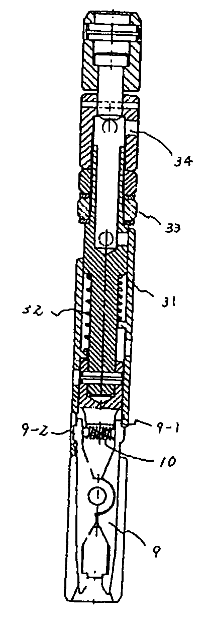
[0039]FIG. 1 is an explanatory view of a water swivel assembly with a built-in over-shot for use in the remote operation wire line core sampling device of the present invention. FIG. 2 is a schematic view for illustrating the operation of a drill head lift device for use in the device of the present invention. FIG. 3 is a general view of a wire line core barrel as assembled. FIG. 4 shows an inner tube assembly thereof, which is raised by the over-shot. FIG. 5 is a general view of a stabilized sea-bottom core drill. FIG. 6 shows an underground over-shot for use in conventional wire line sampling conducted on the ground. FIG. 7 shows an underground water swivel for use in the conventional wire line sampling conducted on the ground.

[0040] For wire line core sampling conducted on the ground, there are produced instruments for vertical boring and instruments for horizontal b...


PUM

PropertyMeasurementUnit
widthaaaaaaaaaa
depthaaaaaaaaaa
gravityaaaaaaaaaa

Abstract

A remote operation wire line core sampling device capable of increasing the efficiency of working and maintaining the wall of a hole by using a stabilized sea-bottom core drill at a sea-bottom and adopting a wire line system, comprising a drill rod held by the chuck of the sea-bottom core drill, a wire line core barrel having, at the tip thereof, a bit for annularly drilling a ground, an inner tube assembly detachably incorporated in the wire line core barrel, and an over-shot assembly (5) having a function for the engagement thereof with a spear head part at the top end of the inner tube assembly. The device also comprises a water swivel (18) in which water supply ports (3) and (4) are formed at the upper and lower parts thereof and a modified built-in type over-shot assembly (4) are formed at the upper and lower parts thereof and a modified built-in type over-shot assembly (5) is incorporated therein so as to reside at the intermediate part thereof.

Description

BACKGROUND ART [0001] The present invention relates to a remote operation wire line core sampling device equipped with a core barrel for investigating bed rocks and deposits at the sea-bottom by using a stabilized sea-bottom core drill. [0002] In conventional sea bed sampling, there are two methods, i.e., one is a method for collecting samples on the sea-bottom surface by using a dredge that linearly collects samples from the sea-bottom surface, a grab that collects samples spread over a given width from a given place on the sea bottom surface, and the other is a method for collecting samples at a given depth from the sea bottom surface. In a method generally adopted when taking samples at a depth from the sea-bottom surface, a tool called a corer is used, and a sampling tube called a core barrel is pierced through the bottom material of the sea bed to take the samples. While the corer, which utilizes its own gravity and initial piercing velocity, can pierce the ground by ten and se...

Claims


Application Information

Patent Timeline
Patent Type & Authority Applications(United States)
IPC IPC(8): E21B25/10E02D1/04E21B25/02G01N1/08
CPCE21B25/02
Inventor KADOMOTO, YUKIOYAMANAKA, ISAOTANAKA, HIROSHITSUCHIYA, TAKAHIKO
Owner MITSUI ENG & SHIPBUILD CO LTD
Learn More