Lighting control circuit for vehicle lighting fixture

a technology for controlling circuits and lighting fixtures, applied in process and machine control, electric devices, instruments, etc., can solve problems such as power consumption, failure of attempt inability to detect wire breakage, so as to simplify circuit configuration, reliably detect faults, and reliably detect faults

Inactive Publication Date: 2006-08-03
KOITO MFG CO LTD
View PDF2 Cites 84 Cited by
  • Summary
  • Abstract
  • Description
  • Claims
  • Application Information

AI Technical Summary

Benefits of technology

[0018] (Operation) In a process where light emission energy is supplied to the plurality of semiconductor light sources connected in series with each other, relative comparison is made between the voltage applied to all of the semiconductor light sources and the voltage applied to the part of the semiconductor light sources. For example, when the ratio of the two voltages changes, it is possible to detect a fault in any semiconductor light source other than at least part of the semiconductor light sources (semiconductor light sources to be compared) among the plurality of semiconductor light sources. That is, it is possible to detect a fault in any semiconductor light source other than at least part of the semiconductor light sources without detecting voltages applied to each semiconductor without individually detecting a voltage applied to each semiconductor light source. This makes it possible to simplify the circuit configuration.
[0034] According to the sixth aspect, it is possible to more reliably detect a fault in any one of the plurality of semiconductor light sources.

Problems solved by technology

When a wire break occurs inside the LED, an attempt to detect the wire break could fail.
Thus, the wire break may not be detected.
The voltages rises so that power consumption in the Zenor diode increases, which could result in thermal breakdown of the Zenor diode, thus lowering the Zenor voltage below the forward voltage of the LED in a thermally stable fashion.
Thus, it may not be possible to reliably detect a wire break in an LED only by monitoring a voltage drop in a resistor serially connected to a light source unit.
The output voltage is within the output voltage range permitted for a switching regulator, so that only monitoring the output voltage of a switching regulator cannot detect a short-circuit fault.
In other words, considering variations in the LED voltage, simply monitoring the absolute value of the output voltage of a switching regulator may not detect a short-circuit fault on one of the LEDS.
When one of the LEDs goes faulty due to a short-circuit, for example, when one LED does not illuminate due to a short-circuit fault, the lighting fixture is emitting light although the desired light distribution is not satisfied.
In this approach, however, the number of short-circuit fault detection circuits increases and wiring becomes thicker as the number of LEDs becomes greater, which complicates the circuit configuration.

Method used


Image

  • Lighting control circuit for vehicle lighting fixture
  • Lighting control circuit for vehicle lighting fixture
  • Lighting control circuit for vehicle lighting fixture

Examples


second embodiment

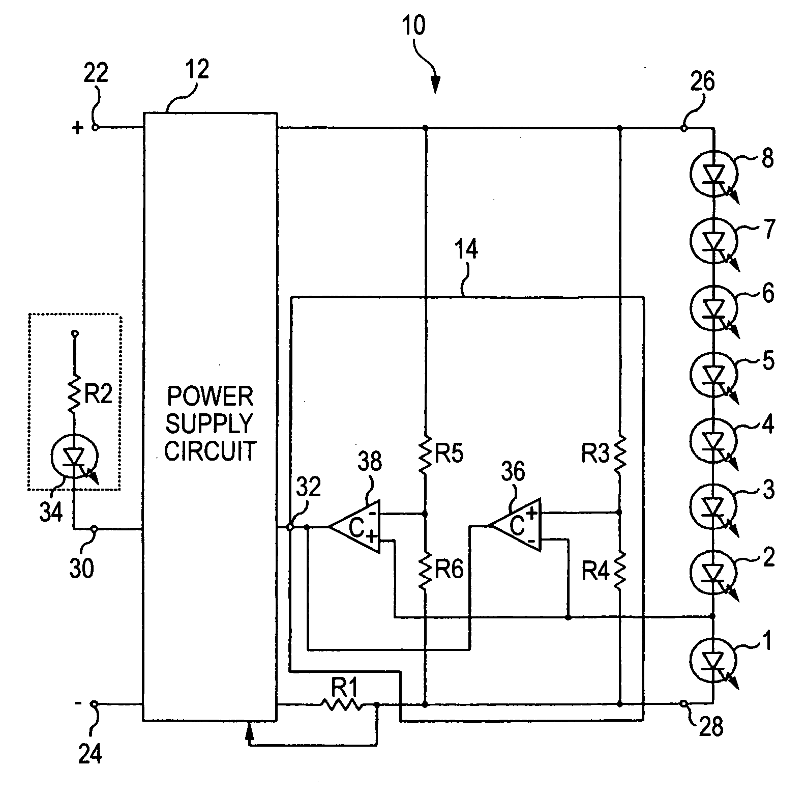
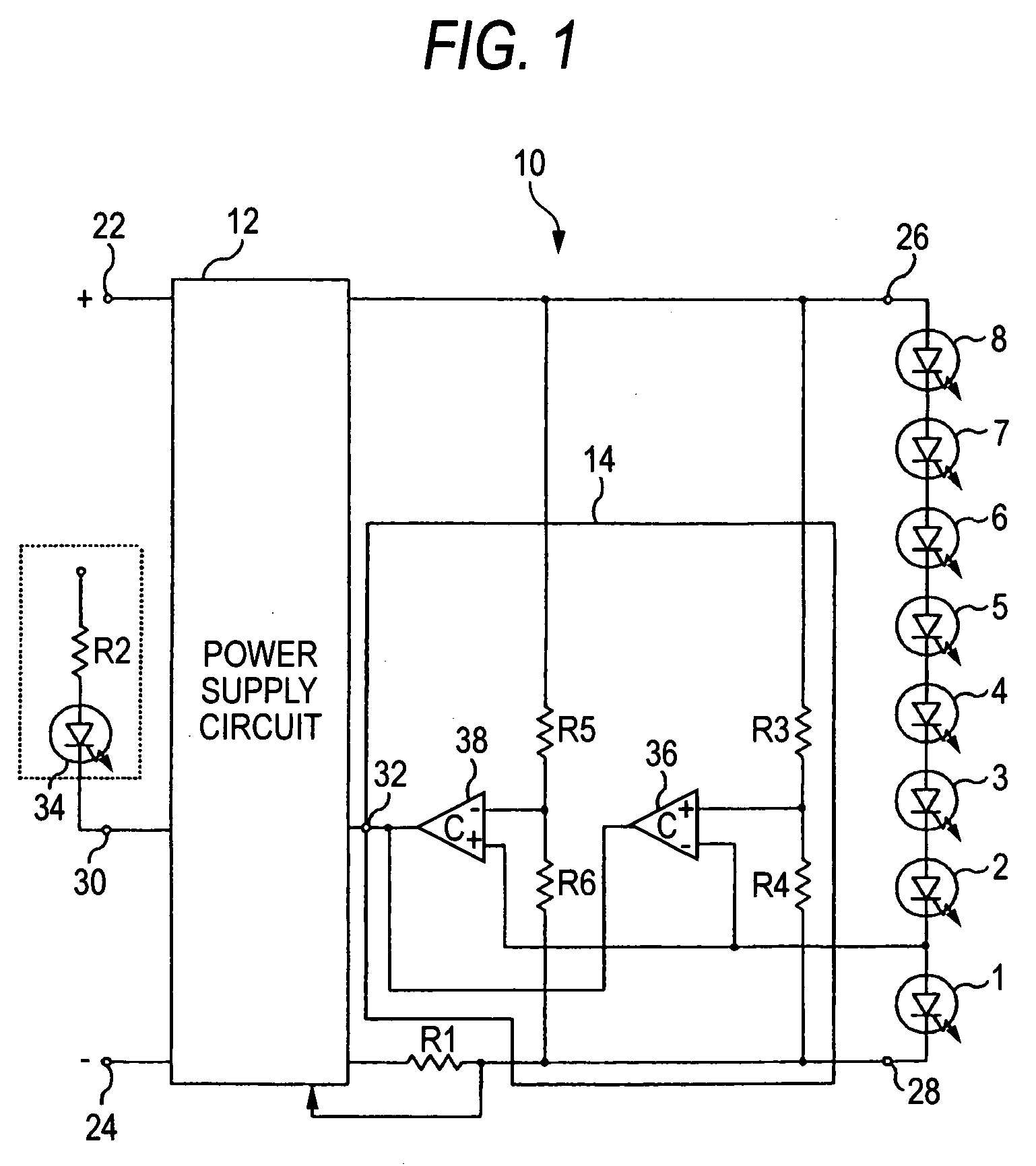
[0059] Next, the invention will be described in accordance with FIG. 3. This embodiment includes a fault detection circuit 40 in place of the fault detection circuit 14. The remaining configuration is the same as that shown in FIG. 1.

[0060] The fault detection circuit 40 makes relative comparison between a voltage applied to the whole of the LEDS 1 through 8 and part of the LEDs 1 through 8 (LED 1) as well as making relative comparison between a voltage applied the part of the LEDs 1 through 8 (LED 1) and a voltage applied to other part of the LEDs different from the part of the LEDS (LED 1) to detect a fault in any one of the LEDs 1 through 8 based on the result of the comparison.

[0061] In particular, the fault detection circuit 40 has resistors R3, R4 and a comparator 36 as well as resistors R7, R8, R9, R10 and a differential amplifier 42 and a comparator 44. The resistors R3 and R4 divides the voltage applied to the whole of the LEDs 1 through 8 and applies the obtained voltage ...

third embodiment

[0066] Next, the invention will be described in accordance with FIG. 4. This embodiment includes a fault detection circuit 46 in place of the fault detection circuit 14. The remaining configuration is the same as that shown in FIG. 1.

[0067] The fault detection circuit 46 makes relative comparison between a voltage applied to the whole of the LEDs 1 through 8 and a voltage applied to part of the LEDs (LED 1) as well as making relative comparison between a voltage applied to part of the LEDs (LED 1) and a set voltage (comparison between absolute values) to detect a fault in any one of the LEDs 1 through 8 based on the result of the comparison.

[0068] In particular, the fault detection circuit 46 has resistors R3, R4 and comparators 36, 37 and a power supply 50.

[0069] The resistors R3 and R4 are set to the same resistance values as those in FIG. 1. The comparator 36 makes relative comparison between a voltage applied to the whole of the LEDs 1 through 8 and a voltage applied across th...

fourth embodiment

[0073] Next, the invention will be described in accordance with FIG. 5. This embodiment includes a fault detection circuit 52 in place of the fault detection circuit 14 and uses the most upstream LED 8 as a target of fault detection in place of the LED 1. The remaining configuration is the same as that shown in FIG. 1.

[0074] The fault detection circuit 52 makes relative comparison between a voltage applied to the whole of the LEDs 1 through 8 and a voltage applied to part of the LEDs (LED 8) as well as making relative comparison between a voltage applied to part of the LEDs (LED 8) and a set voltage (comparison between absolute values) to detect a fault in any one of the LEDs 1 through 8 based on the result of the comparison.

[0075] In particular, the fault detection circuit 52 has resistors R5, R6, comparators 38, 54 and a power supply 50.

[0076] The resistors R5 and R6 are set to the same resistance values as those in FIG. 1. A voltage divided by the resistors R5, R6 is applied to...


PUM


Abstract

Relative comparison is made between a voltage applied to the whole of the first through eighth LEDs and a voltage applied to the first LED by a comparator. When the voltage applied to the whole of the LEDs has relatively dropped with respect to the voltage applied to part of the LEDs, the comparator outputs a Low Level signal, assumes an abnormality that accompanies a short-circuit fault in any one of the LEDs and causes a ninth LED to illuminate. Meanwhile, relative comparison is made between a voltage applied to the whole of the first through eighth LEDs and a voltage applied to the first LED by another comparator. When the voltage applied to the whole of the LEDs has relatively dropped with respect to the voltage applied to part of the LEDs, the comparator outputs a Low Level signal, assumes an abnormality that accompanies a short-circuit fault in the first LED and causes a ninth LED to illuminate.

Description

CROSS-REFERENCE TO RELATED APPLICATIONS [0001] This application is based upon and claims the benefit of priority from the prior Japanese Patent Applications No. 2005-022581, filed on Jan. 31, 2005, the entire contents of which are incorporated herein by reference. BACKGROUND OF THE INVENTION [0002] 1. Field of the Invention [0003] The present invention relates to a lighting control circuit for a vehicle lighting fixture and in particular to a lighting control circuit designed to control lighting of a semiconductor light source including a semiconductor light-emitting device. [0004] 2. Description of the Related Art [0005] In the related art, a vehicle lighting fixture is known that uses a semiconductor light-emitting device such as an LED (Light Emitting Diode). This type of vehicle lighting fixture mounts a lighting control circuit for controlling lighting of an LED. [0006] A lighting control circuit has been proposed that is, in a configuration where a plurality of LEDs are serial...

Claims


Application Information

Patent Timeline
Patent Type & Authority Applications(United States)
IPC IPC(8): H02G3/00B60Q1/00B60Q11/00H01L33/00H05B37/02H05B45/50
CPCB60Q11/005H05B33/0815H05B33/0887H05B45/50H05B45/382
Inventor ITO, MASAYASUSHIOTSU, FUMINORI
Owner KOITO MFG CO LTD
Why Eureka
Try Eureka