[0013] Method (C) induces rapid
light emission of the discharge lamp by the transient
power control. In this case, the
control circuit is complicated in configuration; or, consideration must be given to a structure of a
bulb, such as increasing a
diameter of an
electrode of the
bulb. Put another way, in view of influences on a useful life, and the like,
power control is preferably performed at a rated power value or within an allowable range centered on the rated power value, even when such power control requires a starting time, which is of at least a certain length, rather than a transient power control through which lighting is started under a condition where an excessive load is applied on the discharge lamp.
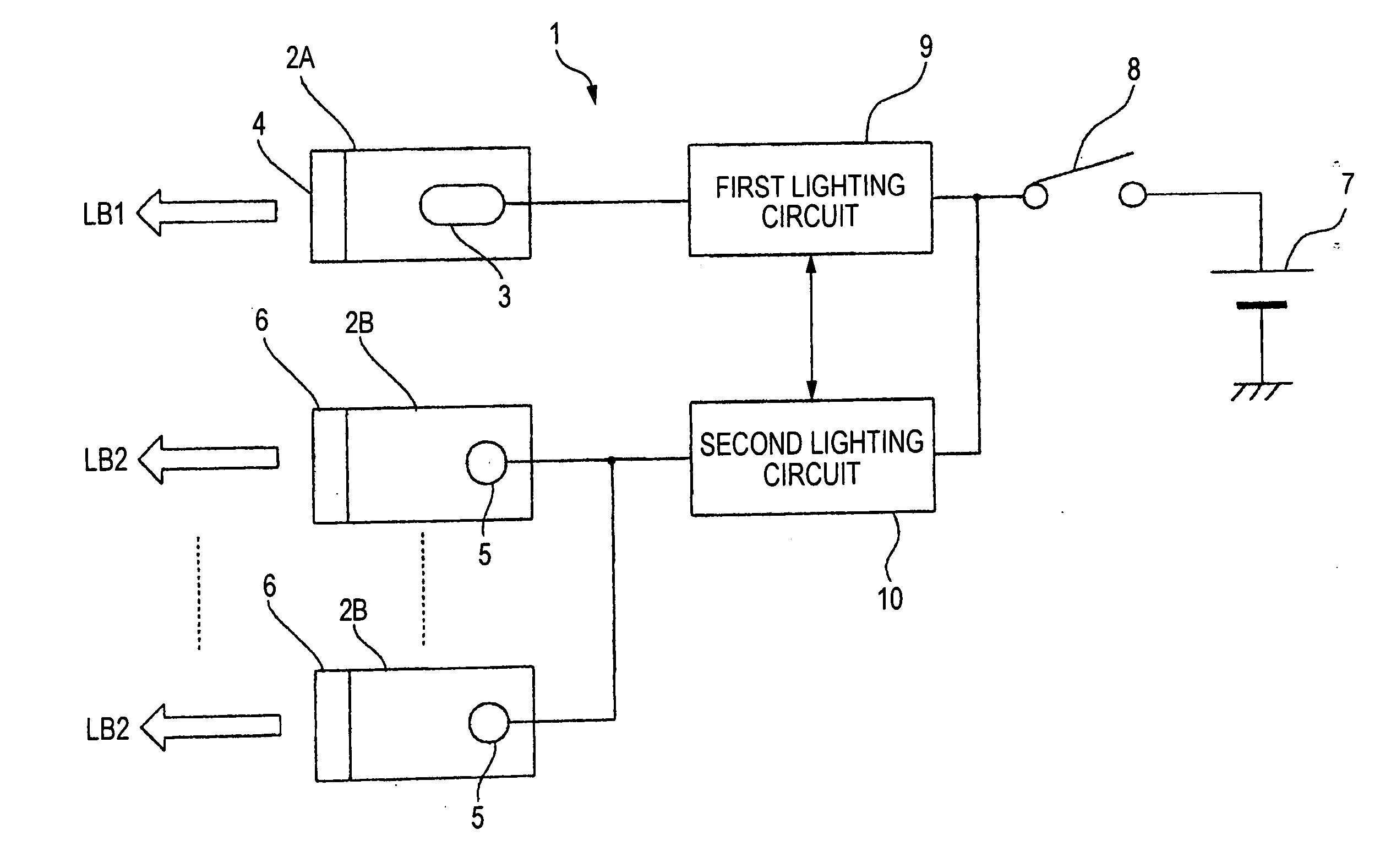
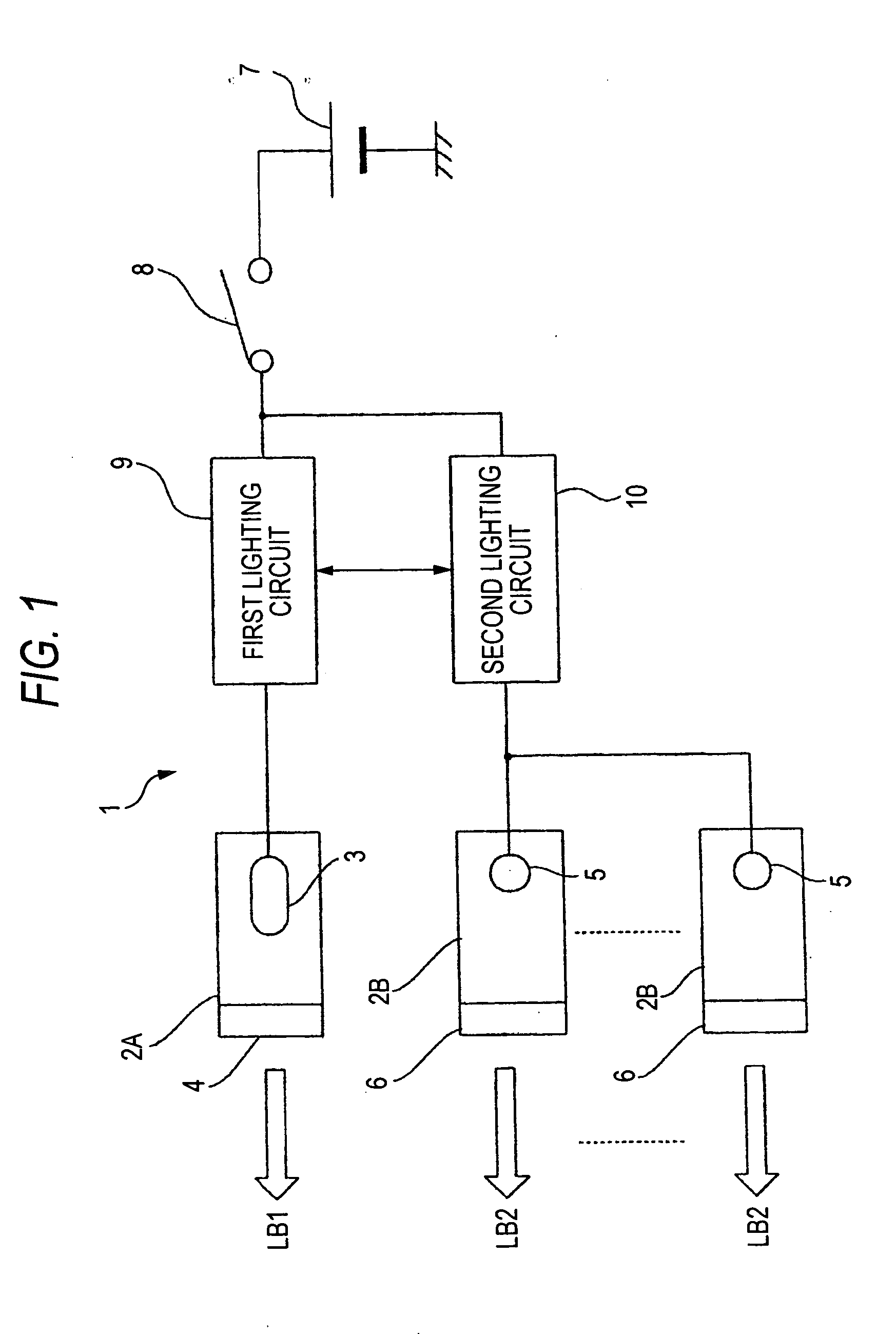
[0015] The invention is a vehicle headlamp having a first lamp unit which employs a discharge lamp as a light source, and a second lamp unit which employs a semiconductor light-emitting element as a light source. The vehicle head lamp can be configured such that a period of time required for lighting the lamp unit is made shorter than a period of time required from a point in time when lighting of the first and second lamp units is started substantially simultaneously until the discharge lamp has transitioned to a steady lighting state; and illumination light patterns originating from the respective lamp units are superimposed so as to obtain a low-beam light distribution.
[0016] Accordingly, when lighting of the first and second lamp units is started, first, the second lamp unit illuminates instantaneously, and thereafter the first lamp unit transitions to the steady lighting state. This obviates an input of power exceeding the rated power during a transient power
control period for reducing a starting time of the discharge lamp. In addition, because of fast transition to illumination or nonillumination, a semiconductor light-emitting element is adequate as a light source for complementing insufficient
luminous energy during starting of a discharge lamp. Since a low-beam light distribution can be obtained by use of illumination light patterns respectively originating from the first and second lamp units, a problem of a low utilization ratio of the light source does not arise (a light
distribution pattern is formed through
combined use with the discharge lamp rather than causing the light-emitting element to illuminate temporarily).
[0013] Method (C) induces rapid
light emission of the discharge lamp by the transient power control. In this case, the
control circuit is complicated in configuration; or, consideration must be given to a structure of a
bulb, such as increasing a
diameter of an
electrode of the bulb. Put another way, in view of influences on a useful life, and the like, power control is preferably performed at a rated power value or within an allowable range centered on the rated power value, even when such power control requires a starting time, which is of at least a certain length, rather than a transient power control through which lighting is started under a condition where an excessive load is applied on the discharge lamp.
[0039] A semiconductor light-emitting element 5; e.g., a
white light-emitting
diode, is used as a light source of each of the second lamp units 2B. The
color temperature of the semiconductor light-emitting element 5 falls within a range of 4,000 to 6,500 K. The light-emitting diode has a
color temperature close to that of the HID lamp. Therefore, even when a light
distribution pattern is formed by superimposing the light originating from the light-emitting diode and the light originating from the discharge lamp, the pattern provides a less unnatural
sensation. However, compared with the discharge lamp, the light-emitting diode has a low intensity. Therefore, a plurality of lamp units are required for obtaining a predetermined
luminous flux.

