Spin-injection magnetic random access memory

a magnetic random access and magnetic technology, applied in the direction of digital storage, instruments, semiconductor devices, etc., can solve the problems of large memory capacity, inability to reduce pulse current to the value required, and increase electric power consumption

Active Publication Date: 2006-08-03
KK TOSHIBA
View PDF10 Cites 40 Cited by
  • Summary
  • Abstract
  • Description
  • Claims
  • Application Information

AI Technical Summary

Benefits of technology

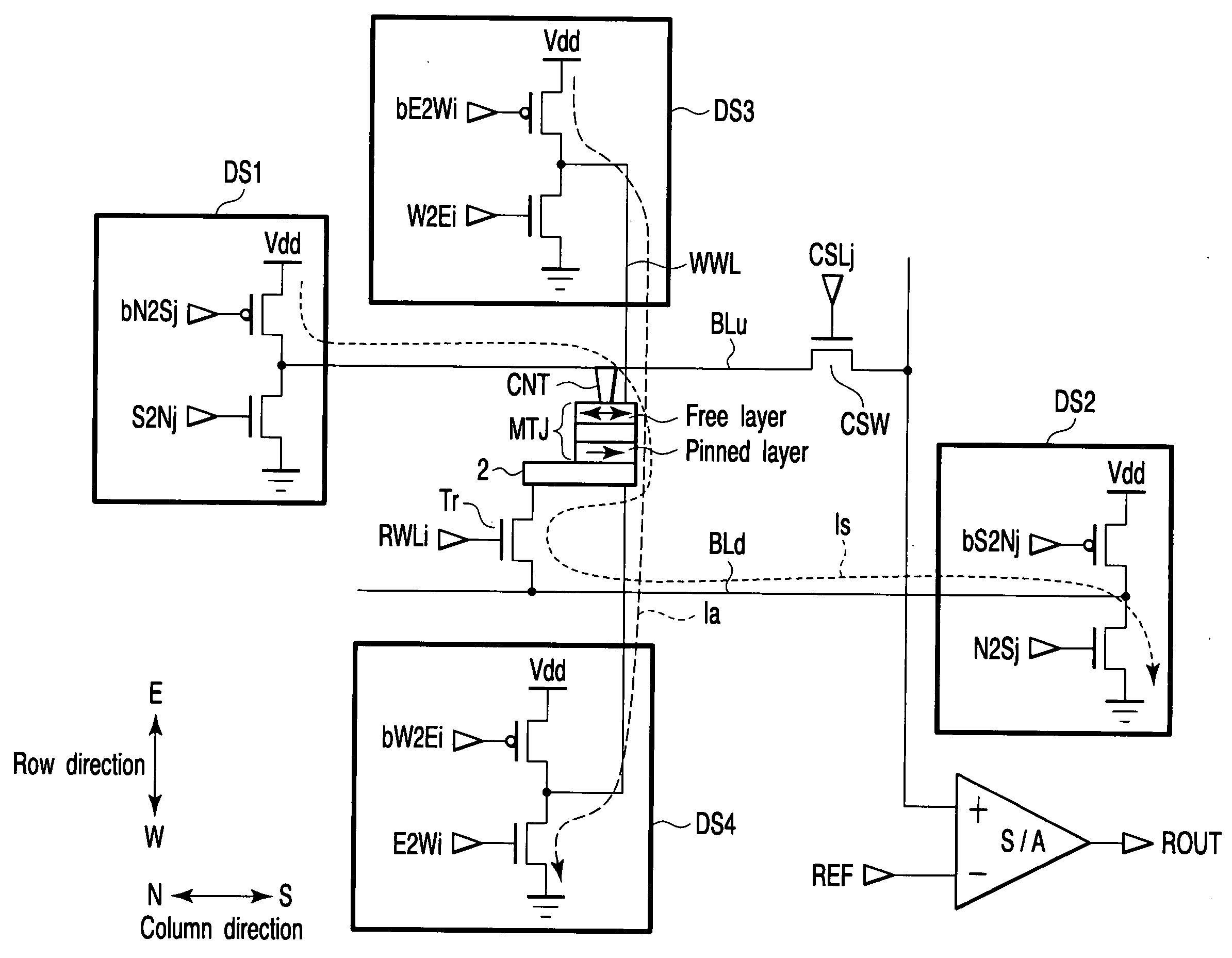
[0023] A spin-injection magnetic random access memory according to one aspect of the present invention comprises: a magnetoresistive element having a magnetic fixed layer whose magnetization direction is fixed, a magnetic recording layer whose magnetization direction can be changed by injecting spin-polarized electrons, and a tunnel barrier layer which is provided between the magnetic fixed layer and the magnetic recording layer; a bit line which passes spin-injection current through the magnetoresistive element, the spin-injection current being used for generation of the spin-polarized electrons; a writing word line through which assist current is passed, the assist current being used for the generation of an assist magnetic field in a magnetization easy-axis direction of the magnetoresistive element; a first driver / sinker which is connected to the bit line; a second driver / sinker which is connected to the writing word line; a first decoder which controls the first driver / sinker to determine a direction of the spin-injection current according to a value of writing data in writing data in the magnetoresistive element while determining timing of cutoff of the spin-injection current; and a second decoder which controls the second driver / sinker to determine the direction of the spin-injection current according to the value of the writing data during the data writing while making the timing of the cutoff of the assist current later than the timing of the cutoff of the spin-injection current.

Problems solved by technology

Therefore, current density of the pulse current supplied to a word line or a bit line is increased, which results in new problems that electric power consumption is increased, large memory capacity is difficult to be realized, and a driver for generating the pulse current is increased in an area.
However, the pulse current cannot still be decreased to a value required for the practical use of the magnetic random access memory, i.e., the values not more than 1 mA.
However, these values are not still enough to realize the magnetic random access memory.

Method used


Image

  • Spin-injection magnetic random access memory
  • Spin-injection magnetic random access memory
  • Spin-injection magnetic random access memory

Examples


first embodiment

(i) First Embodiment

[0111]FIG. 11 shows a first embodiment of the magnetoresistive element.

[0112] In the first embodiment, the magnetoresistive element includes an anti-ferromagnetic layer 3, a first magnetic fixed layer 4, a tunnel barrier layer 5, a magnetic recording layer 6, a non-magnetic metal layer 7, a second magnetic fixed layer 8, and an anti-ferromagnetic layer 9. The magnetic recording layer 6 is arranged on the first magnetic fixed layer 4 through tunnel barrier layer 5. The second magnetic fixed layer 8 is arranged on the magnetic recording layer 6 through the non-magnetic metal layer 7.

[0113] In the first magnetic fixed layer 4, the magnetization state is fixed by exchange interaction bonding between the first magnetic fixed layer 4 and the anti-ferromagnetic layer 3. In the second magnetic fixed layer 8, the magnetization state is fixed by the exchange interaction bonding between the second magnetic fixed layer 8 and the anti-ferromagnetic layer 9. The magnetizatio...

second embodiment

(ii) Second Embodiment

[0123]FIG. 12 shows a second embodiment of the magnetoresistive element.

[0124] The second embodiment is one of modifications of the first embodiment, and the second embodiment differs from the first embodiment in the structure of the second magnetic fixed layer.

[0125] In the second embodiment, the magnetoresistive element includes the anti-ferromagnetic layer 3, the first magnetic fixed layer 4, the tunnel barrier layer 5, the magnetic recording layer 6, the non-magnetic metal layer 7, a second magnetic fixed layer 8SAF, and the anti-ferromagnetic layer 9. The magnetic recording layer 6 is arranged on the first magnetic fixed layer 4 through tunnel barrier layer 5. The second magnetic fixed layer 8SAF and the anti-ferromagnetic layer 9 are arranged on the magnetic recording layer 6 through the non-magnetic metal layer 7.

[0126] In the first magnetic fixed layer 4, the magnetization state is fixed by the exchange interaction bonding between the first magnetic ...

third embodiment

(iii) Third Embodiment

[0138]FIG. 13 shows a third embodiment of the magnetoresistive element.

[0139] In the third embodiment, the magnetoresistive element includes the anti-ferromagnetic layer 3, the first magnetic fixed layer 4, the tunnel barrier layer 5, the magnetic recording layer 6, the non-magnetic metal layer 7, the second magnetic fixed layer 8, and the anti-ferromagnetic layer 9. The magnetic recording layer 6 is arranged on the first magnetic fixed layer 4 through tunnel barrier layer 5. The second magnetic fixed layer 8 is arranged on the magnetic recording layer 6 through the non-magnetic metal layer 7.

[0140] In the first magnetic fixed layer 4, the magnetization state is fixed by the exchange interaction bonding between the first magnetic fixed layer 4 and the anti-ferromagnetic layer 3. In the second magnetic fixed layer 8, the magnetization state is fixed by the exchange interaction bonding between the second magnetic fixed layer 8 and the anti-ferromagnetic layer 9...


PUM


Abstract

A spin-injection magnetic random access memory according to an embodiment of the invention includes a magnetoresistive element having a magnetic fixed layer whose magnetization direction is fixed, a magnetic recording layer whose magnetization direction can be changed by injecting spin-polarized electrons, and a tunnel barrier layer provided between the magnetic fixed layer and the magnetic recording layer, a bit line which passes spin-injection current through the magnetoresistive element, the spin-injection current being used for generation of the spin-polarized electrons, a writing word line through which assist current is passed, the assist current being used for the generation of an assist magnetic field in a magnetization easy-axis direction of the magnetoresistive element, and a driver/sinker which determines a direction of the spin-injection current and a direction of the assist current.

Description

CROSS-REFERENCE TO RELATED APPLICATIONS [0001] This application is based upon and claims the benefit of priority from prior Japanese Patent Application No. 2005-021877, filed Jan. 28, 2005, the entire contents of which are incorporated herein by reference. BACKGROUND OF THE INVENTION [0002] 1. Field of the Invention [0003] The present invention relates to a spin-injection magnetic random access memory in which magnetization reversal is performed with spin-polarized electrons. [0004] 2. Description of the Related Art [0005] In addition to magnetic heads and detection elements such as a magnetic sensor, a magnetoresistive element in which a magnetic film is used has been studied for the use of a storage element in a magnetic random access memory (MRAM), which is of a solid-state magnetic memory. [0006] The magnetoresistive element has a sandwich structure, which includes, e.g., two magnetic metal layers and a dielectric layer arranged there between. In the magnetoresistive element hav...

Claims


Application Information

Patent Timeline
Patent Type & Authority Applications(United States)
IPC IPC(8): G11C11/00
CPCB82Y10/00G11C11/16H01L27/228H01L43/08H10B61/22H10N50/10
Inventor SAITO, YOSHIAKISUGIYAMA, HIDEYUKIINOKUCHI, TOMOAKIIWATA, YOSHIHISA
Owner KK TOSHIBA
Why Eureka
Try Eureka