
Optical information recording medium, method of manufacturing same, and recording method

A technology for recording media and optical information, applied in the direction of optical recording/reproduction/erasing methods, optical recording carriers, optical recording systems, etc., can solve the problem of difficult light and dark identification of optical discs and photodetectors that cannot obtain push-pull values, and cannot focus Follow-up and other problems, achieve good NPPb characteristics, easy high-speed recording, and achieve high-speed recording effects

Inactive Publication Date: 2009-03-04
TAIYO YUDEN KK
View PDF2 Cites 1 Cited by
  • Summary
  • Abstract
  • Description
  • Claims
  • Application Information

AI Technical Summary

Problems solved by technology

[0016] However, recording media using blue lasers require high-density recording, and the physical channel pitch is narrow, and the heat generated during pigment decomposition tends to be transferred to adjacent channels, resulting in deterioration of characteristics.
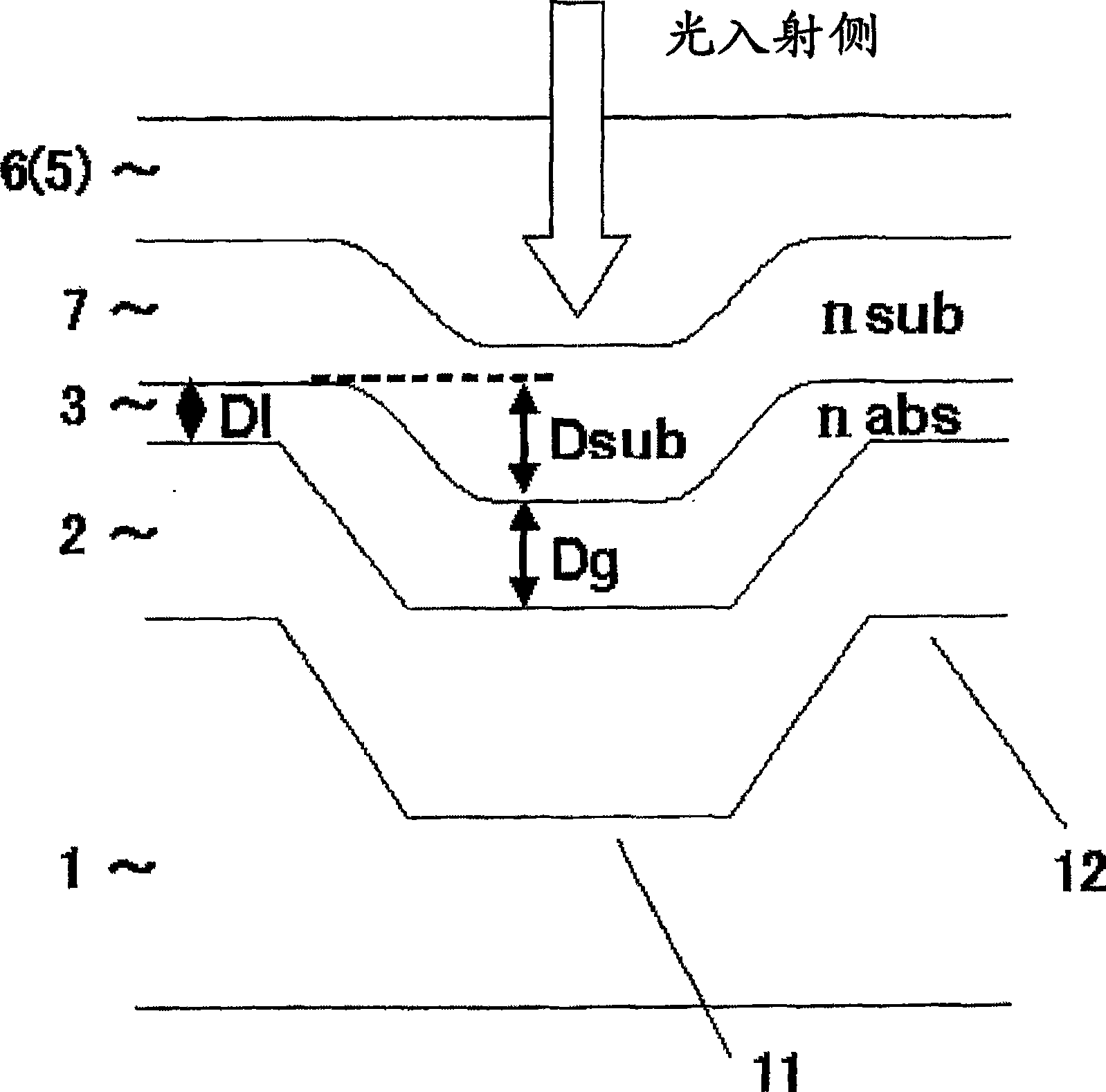
[0017] In addition, although the development of the optical information recording medium by the Low to High method has also been carried out recently, in the blue laser wavelength region, the groove becomes a concave direction with respect to the incidence of the laser beam, and a 0.1 mm light-transmitting layer is provided on the laser beam. In the case of an optical information recording medium on the incident surface, if a pigment of a type whose reflectance changes with the imaginary part k of the complex refractive index before and after recording as the main factor is used, then in the optical information recording by the Low to High method media, causing the push-pull (NPPb) signal to become too high when not recording
[0018] If the push-pull (NPPb) signal becomes too high, in the focus method by the astigmatism method, there is difficulty in distinguishing light and dark of the photodetector, and focus follow-up cannot be performed, or even in the DPP (differential push-pull) method , it is also difficult to identify the light and dark of the photoelectric detector, and it is impossible to follow the tracking and other problems
In addition, it is necessary to use an organic pigment with a large extinction coefficient in the background, and the push-pull value is easily increased due to the groove depth and width of the groove
Also, in this case, since the refractive index is slightly small, push-pull tends to be good, but since it is a pigment with a large extinction coefficient, reflection is likely to occur. good push-pull values ​​for the disc

Method used


Image

  • Optical information recording medium, method of manufacturing same, and recording method
  • Optical information recording medium, method of manufacturing same, and recording method
  • Optical information recording medium, method of manufacturing same, and recording method

Examples


Embodiment 1

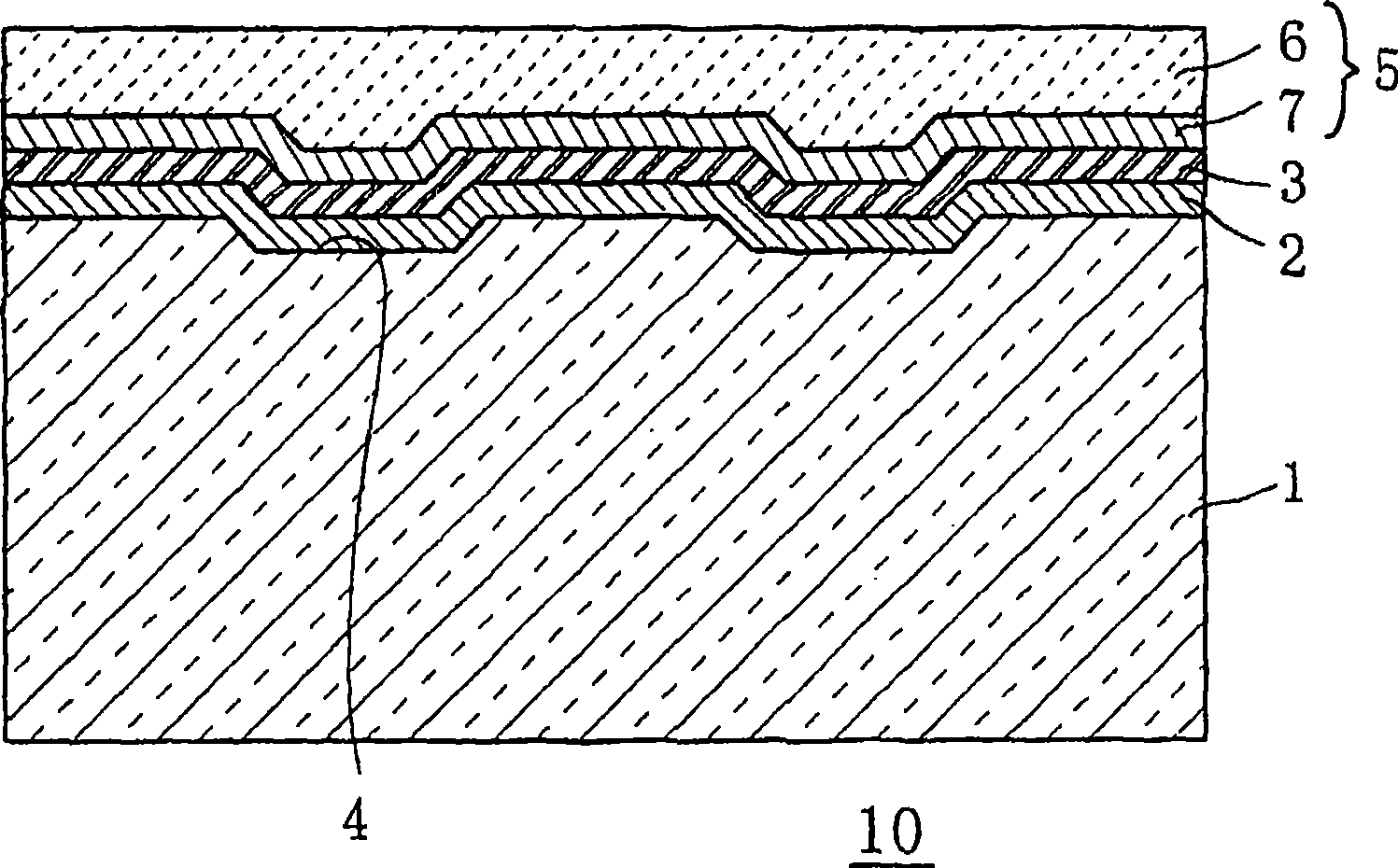
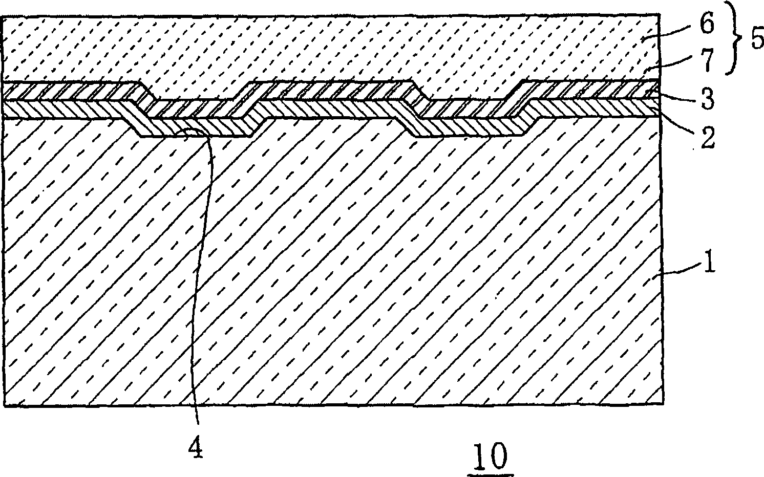
[0137] Grooves with a pitch of 0.32 μm were formed, and a disc-shaped polycarbonate substrate with an outer diameter of 120 mm and a thickness of 1.1 mm was produced. A reflective layer made of Ag alloy was sputtered on this substrate to form a channel with a depth of 45 nm and a width of 110 nm. Then, a pigment solution in which the azo pigment shown in (Chemical Formula 1) was dissolved in a TFP (tetrafluoropropanol) solvent was applied by spin coating, and dried at 80° C. for 30 minutes to form grooves. A recording layer with a film thickness of 35nm and a parting mask thickness of 15nm. Then, sputtering was performed so that the transparent intermediate layer made of aluminum nitride material had a thickness of 30 nm. Then, an optical information recording medium was obtained by bonding a light-transmitting layer made of a 0.1 mm polycarbonate sheet to the surface of the intermediate layer via a transparent adhesive.

[0138] The refractive index n and the extinction coe...

Embodiment 2

[0141] In addition to sputtering the reflective layer on the substrate to form a channel with a depth of 57nm and a width of 110nm, as a recording layer, the azo pigment shown in (Chemical formula 1) and the cyanine pigment shown in (Chemical formula 2) will be dissolved in TFP ( The pigment solution in the tetrafluoropropanol) solvent is applied by the spin coating method, and the maximum film thickness of the groove is 34nm, and the thickness of the parting film is 10nm. Except for the recording layer, it is made the same as the above-mentioned embodiment 1. Thus, an optical information recording medium was obtained.

[0142] The refractive index n and the extinction coefficient k of the recording layer of the optical information recording medium thus obtained were measured with an n, k measuring device (ETA-RT / UV manufactured by Steage ETA-Optik GmbH), and as a result, n was 1.41 , k is 0.35. In addition, the optical phase difference ΔS is 0.49, and the change amount Δk of...

Embodiment 3

[0145] In addition to sputtering the reflective layer on the substrate, a channel with a depth of 35nm and a width of 85nm was formed. As a recording layer, the same pigment solution as in Example 1 was applied by spin-coating, and a groove-maximum film was formed. Except for the recording layer having a thickness of 23 nm and a parting film thickness of 16 nm, an optical information recording medium was obtained in the same manner as in Example 1 above.

[0146]The refractive index n and the extinction coefficient k of the recording layer of the optical information recording medium obtained in this way were measured with an n, k measuring device (ETA-RT / UV manufactured by Steage ETA-Optik GmbH). As a result, n was 1.42 , k is 0.39. In addition, the optical phase difference ΔS is 0.34, and the change amount Δk of the extinction coefficient k is 0.26 when the recording layer is heated using a differential thermal analyzer (TG-DTA), and the extinction coefficient after heating i...


PUM

PropertyMeasurementUnit
wavelengthaaaaaaaaaa
thicknessaaaaaaaaaa

Abstract

Provided are an optical information recording medium and its recording method capable of appropriately recording with a high density and at a high speed by using a recording wavelength in the range from 360 to 450 nm and especially about 400 nm (such as 405 nm). A preferable push-pull signal by performing recording based on the Low to High method instead of the conventional High to Low method and setting the pit reflectance higher than the reflectance of the non-pit region, the maximum film thickness of the recording layer in the track region where pits are arranged in the range from 25 to 60 nm, and the maximum film thickness of the recording layer in the region adjacent to the track in the range from 5 to 30 nm. Moreover, it is preferable that the film thickness of the reflection layer be in the range from 120 to 180 nm and the groove width of the reflection layer be in the range from 85 to 150 nm.

Description

technical field [0001] The present invention relates to a write-once optical information recording medium and a recording method thereof, in particular to an optical information recording medium and a manufacturing method thereof for recording with laser light (blue laser, blue laser) with a wavelength of 360 to 450 nm generated by a semiconductor laser and recording method. Background technique [0002] Currently, a write-once optical information recording medium using blue laser light near 360-450 nm (for example, about 405 nm) on the short-wave side has been developed (see Patent Document 1: Japanese Unexamined Patent Application Publication No. 11-120594). [0003] The optical information recording medium uses an organic pigment compound on the optical recording layer. The organic pigment compound is decomposed or modified by absorbing laser light. As a modulation degree, the optical characteristic of the laser light in the recording and reproduction wavelength is change...

Claims


Application Information

Patent Timeline
Patent Type & Authority Applications(China)
IPC IPC(8): G11B7/24G11B7/244G11B7/24035G11B7/24079G11B7/24085G11B7/246G11B7/2467G11B7/247G11B7/2472G11B7/249G11B7/2495G11B7/258G11B7/259
CPCG11B7/266G11B7/24079G11B7/24035G11B7/24085G11B7/2495G11B7/246G11B7/259G11B7/2472G11B2007/24612G11B7/2467G11B7/244G11B7/2407G11B7/0045G11B7/007
Inventor 松田勋原风美
Owner TAIYO YUDEN KK
Learn More