
Optical information recording medium and method of producing the same

a technology of optical information and recording medium, which is applied in the field of optical information recording medium, can solve the problems of inability to obtain a proper refractive index of dye thin film, inability to achieve satisfactory practicability of high-to-low recording commercial products, etc., to achieve excellent optical properties, high refractive index, and easy generation of differences in refractive index

Inactive Publication Date: 2007-11-22
TAIYO YUDEN KK
View PDF6 Cites 0 Cited by
  • Summary
  • Abstract
  • Description
  • Claims
  • Application Information

AI Technical Summary

Benefits of technology

[0039] An object of at least one embodiment of the present invention is to provide an optical information recording medium in which a thin film having a high refractive index (e.g., 1.7 to 2.8) and satisfactory optical properties can be formed, and a method of producing the same.
[0040] An object of at least one embodiment of the present invention is to provide an optical information recording medium in which an optical recording layer containing a J-aggregate can be formed by a simple method (spin-coating method), and a method of producing the same.
[0041] An object of at least one embodiment of the present invention is to provide an optical information recording medium in which a dye material can be applied using a solvent that does not corrode a substrate material, such as a polycarbonate resin, and a method of producing the same.
[0043] As a result of intensive studies, the present inventors have found the following. In the known CD-R and DVD-R / +R discs, an amorphous thin film of dye molecules is used, and the dye molecules are randomly oriented in the thin film. In the thin film in which the molecules are randomly oriented, intermolecular interaction is weak and the thin film shows a broad absorption spectrum. In contrast, in a J-aggregate, molecules form a minute molecular aggregate while being regularly arrayed by intermolecular interaction. Therefore, the absorption spectrum has a small full width at half maximum, and the absorbance is larger than that in the case where molecules are randomly oriented. Accordingly, by preparing a J-aggregate thin film, a dye thin film having a high refractive index (n) and a low extinction coefficient (k) can be formed. Accordingly, it is expected that a high-to-low optical information recording medium can be realized. Furthermore, when recording is performed by breaking an aggregate by irradiation of a recording laser beam, the quantity of heat generated by the decomposition can be decreased and thermal interference can be suppressed.
[0055] In the optical information recording medium according to at least one embodiment of the present invention and the method of producing the same, the optical recording layer includes a dye film containing a specific dye material of the mono(aza)methine compound represented by general formula [1] or [2] and an acid. Accordingly, a uniform thin film containing a J-aggregate of the dye molecules can be formed even by a simple spin-coating method. When the J-aggregation occurs, a peak in the absorption spectrum of the dye thin film becomes sharper, the full width at half maximum of the peak is decreased, and the peak is shifted to the long-wavelength side. Consequently, a thin film having a high refractive index can be formed. Accordingly, when the aggregated dye is thermally decomposed by light absorption derived from the J-aggregation of the dye molecules, a difference in the refractive index can be easily generated before and after recording. Furthermore, since this thermal decomposition of the J-aggregate of the dye is an endothermic reaction, control of heat dissipation, which is required in a known case of an exothermic reaction, need not be performed.
[0056] That is, a recording material thin film having excellent optical properties, such as a high refractive index and a large difference in the refractive index before and after recording, and a thermal property corresponding to an endothermic reaction, can be uniformly formed. Furthermore, the aggregate thin film is formed by a simple spin-coating method, and thus, an optical information recording medium having excellent properties can be produced without changing a known process.

Problems solved by technology

However, among the HD DVD-R discs and the Blu-ray Disc-R discs (hereinafter, these are also referred to as “blue discs” or the like) onto and from which recording and reproducing are performed with a laser beam having a wavelength of 405 nm, high-to-low recording commercial products having satisfactory practicability have not yet been developed.
This is because a dye thin-film having a proper refractive index has not been obtained.
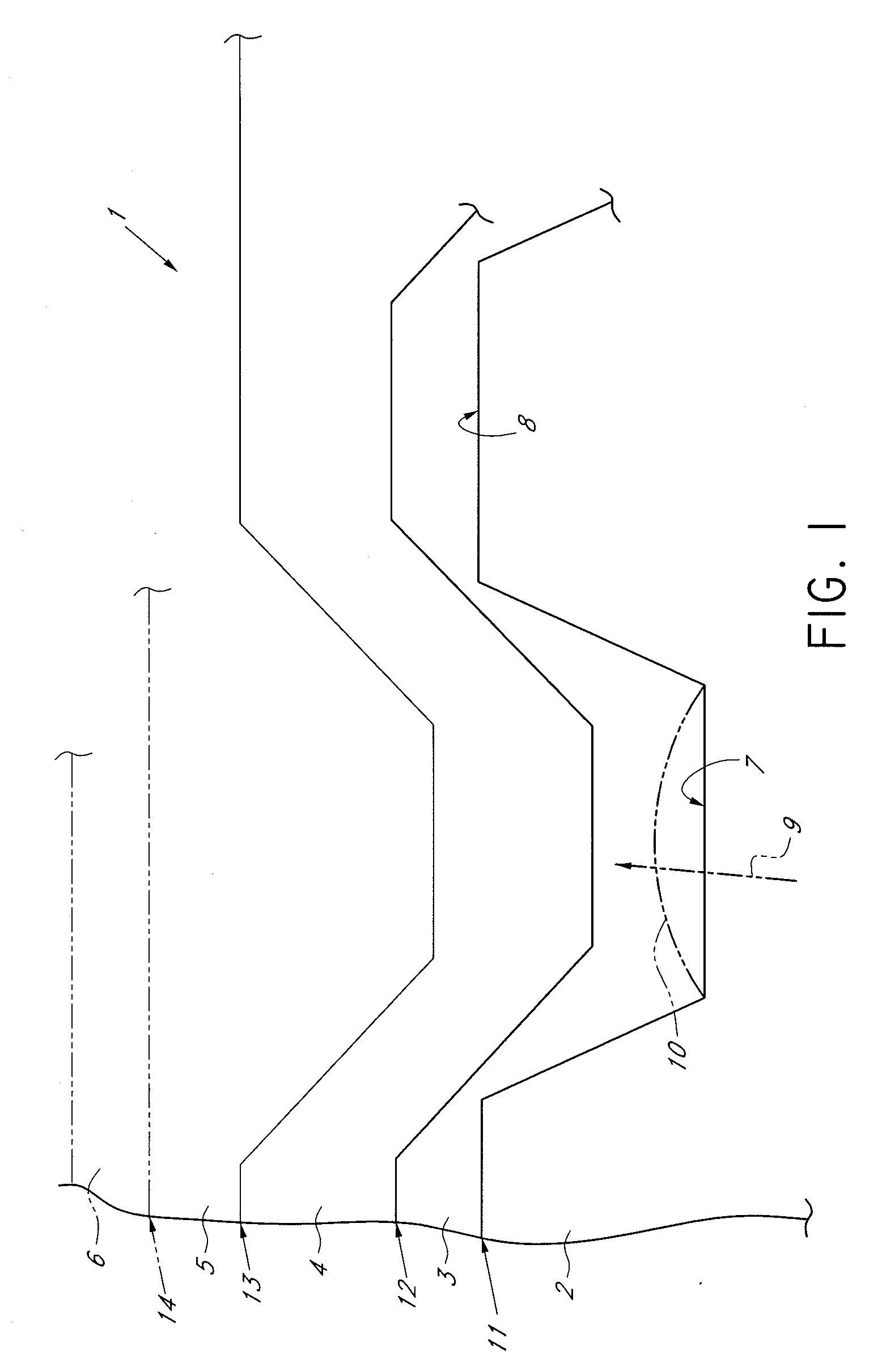
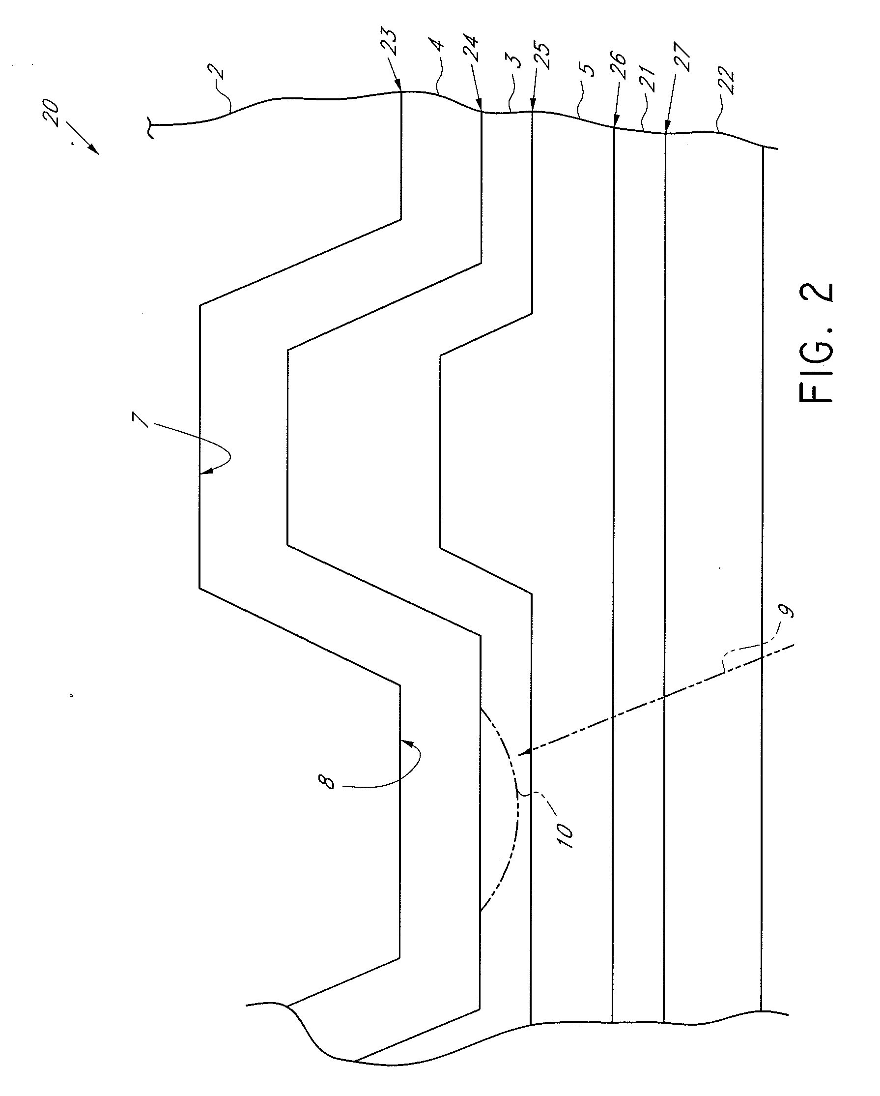
Consequently, a problem of thermal strain easily occurs, resulting in variations among the recording pits 10.
In addition, the output power of a semiconductor laser for emitting the laser beam 9 is limited.
However, in such an organic compound, optical properties (in particular, refractive index) for a blue laser wavelength, e.g., 405 nm are normally mediocre.
However, in this case, the absorption coefficient, that is, the refractive index, is decreased, and therefore, a high degree of modulation cannot be achieved during reproducing.
It is generally known that as the maximum absorption wavelength (λmax) is decreased, the molar absorptivity (ε) is decreased, and that it is difficult to develop a dye that can be used to realize high-to-low-type optical recording discs for a short recording wavelength, which is used for the blue discs or the like.
Therefore, high-quality recording cannot be performed because of thermal interference resulting in the recording pits becoming enlarged.
However, since skilled control is necessary during the formation of the film, this method is disadvantageous in terms of time and cost.
However, the dip method is disadvantageous in that it is difficult to form a uniform thin film and stably maintain the thin film.
However, since molecules are present in various states under a simple coating condition, it is difficult to control the aggregation.
In this technique, satisfactory dye physical properties as a dye thin film used for an optical information recording medium cannot be obtained because the concentration of the cyanine dye in the thin film is decreased by the silica.
Therefore, the dye thin film is not suitable for use in an optical information recording medium.
That is, it is difficult to apply this technique to an optical information recording medium.
In this technique, satisfactory dye physical properties as a dye thin film used for an optical information recording medium cannot be obtained because the concentration of the cyanine dye in the thin film is decreased by the polymer material.
Therefore, the dye thin film is not suitable for use in an optical information recording medium.
That is, it is difficult to apply this technique to an optical information recording medium.
The technique disclosed in this patent document is disadvantages in that the squarylium dye has a poor solubility in organic solvents.
Accordingly, it is difficult to ensure the solubility in a solvent that does not corrode the polycarbonate resin, which is a material of the substrate 2 of the optical information recording medium.
That is, it is difficult to obtain a sufficient thickness required for a dye thin film used for an optical information recording medium.
Accordingly, the design of the squarylium dye molecules is complex because both the solubility and the degree of aggregation of the molecules must be considered.
That is, it is difficult to apply this technique to an optical information recording medium.
However, it is difficult to obtain a sufficient thickness required for a dye thin film used for an optical information recording medium.
In addition, it is very difficult to apply the LB method to the current optical information recording medium.
However, at present, a simple preparation method in which aggregation can be easily controlled has not yet been established.
The J-aggregate thin films can be relatively easily prepared by the LB method or the dip method, but these methods are disadvantageous in that skilled control is necessary or a uniform thin film cannot be stably obtained.
On the other hand, although thin films can be easily formed by the spin-coating method, it is difficult to prepare J-aggregate thin films by the spin-coating method.

Method used


Image

  • Optical information recording medium and method of producing the same
  • Optical information recording medium and method of producing the same
  • Optical information recording medium and method of producing the same

Examples


example 1

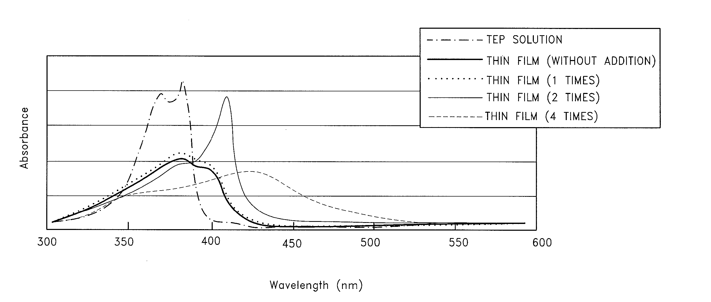
[0097] First, 2.0 g of a monomethine cyanine compound (Compound I) represented by formula [9] below was fed in a 100-mL flask. Phosphoric acid was then added in an amount of 0 times (without addition), 0.5 times (178 mg) (more specifically, the molar ratio of H+ to Compound I was 0.5 (1 molecule of Compound I : 0.5 hydrogen ion H+), and this also applies to the following cases), 1 times (357 mg), 2 times (714 mg), or 4 times (1,428 mg) the amount of Compound I. Furthermore, 2,2,3,3-tetrafluoro-1-propanol (TFP) was added to each flask so that the total volume reached 100 mL, and the mixture was sufficiently stirred to dissolve the compound. Thus, monomethine dye compositions each containing Compound I in a concentration of 20 g / L were prepared.

[0098] Subsequently, 5 mL of each solution of the above monomethine dye composition was dripped to a 1,000-mL volumetric flask, and 2,2,3,3-tetrafluoro-1-propanol was then added to the flask so that the total volume reached 1,000 mL. The mixtu...

examples 2 to 5

[0110] Monomethine cyanine dyes (Compounds II, III, IV, and V) represented by formulae [12], [13], [14], and [15], respectively, were used instead of Compound I in Example 1. As in the above-described case of Compound I, phosphoric acid was added in an amount of 1 times or 2 times the amount of each compound to prepare solutions. Each of these solutions was applied on a single plate by spin coating as in Example 1. The spectrum of each thin film of Compound II, III, IV, or V formed on the single plate was measured. FIGS. 7, 8, 9, and 10 show the results of Compounds II, III, IV, and V, respectively.

[0111] Referring to the absorption spectra of thin films on the single plates in FIGS. 7 to 10, when the absorption spectrum shown by the thin solid line (thin film (with addition of phosphoric acid in an amount of 2 times the amount of compound)) was compared with that shown by the dotted line (thin film (with addition of phosphoric acid in an amount of 1 times the amount of compound)),...

example 6

[0112] First, 2.0 g of a monoazamethine cyanine compound (Compound VI) represented by formula [16] below was fed in a 100-mL flask. Phosphoric acid was then added in an amount of 0 times (without addition), 0.5 times (160 mg) (more specifically, the molar ratio of H+ to Compound VI was 0.5 (1 molecule of Compound VI 0.5 hydrogen ion H+), and this also applies to the following cases), 1 times (320 mg), 2 times (640 mg), or 4 times (1,280 mg) the amount of Compound VI. Furthermore, 2,2,3,3-tetrafluoro-1-propanol (TFP) was added to each flask so that the total volume reached 100 mL, and the mixture was sufficiently stirred to dissolve the compound. Thus, monoazamethine dye compositions each containing Compound VI in a concentration of 20 g / L were prepared.

[0113] Subsequently, 5 mL of each solution of the above monoazamethine dye composition was dripped to a 1,000-mL volumetric flask, and 2,2,3,3-tetrafluoro-1-propanol was then added to the flask so that the total volume reached 1,000 ...


PUM


Abstract

An optical information recording medium includes an optical recording layer onto which information is to be recorded by a laser beam, wherein the optical recording layer includes a dye film containing a specific mono(aza)methine compound and an acid and is directly provided on a surface of a layer that allows transmittance of the laser beam therethrough, the surface being arranged opposite a surface of the layer through which the laser beam enters. The optical recording layer is formed by applying a solution of a mono(aza)methine dye composition containing the acid and the specific mono(aza)methine dye compound by a spin-coating method.

Description

BACKGROUND OF THE INVENTION [0001] 1. Field of the Invention [0002] The present invention relates to an optical information recording medium and a method of producing the same. In particular, the present invention relates to an optical information recording medium that includes at least an optical recording layer containing a light-absorbing substance and the like, and that can be used for the optical recording layer of an optical information recording medium onto and from which writing and reproducing can be performed with a high density and at a high speed using a semiconductor laser that emits a red laser beam having a wavelength in the range of 750 to 830 nm, a short-wavelength red laser beam having a wavelength in the range of 640 to 680 nm (for example, 650 to 665 nm), or a blue laser beam having a shorter wavelength in the range of about 350 to 500 nm (for example, about 405 nm), and a method of producing the optical information recording medium. [0003] 2. Description of the ...

Claims


Application Information

Patent Timeline
IPC IPC(8): G11B7/24G11B7/24035G11B7/247G11B7/249
CPCG11B7/2472G11B7/246
Inventor KODAIRA, TAKUOAMANO, AKIO
Owner TAIYO YUDEN KK
Learn More