Drill for chip removing machining

a technology for drilling holes and chip jamming, which is applied in the direction of twisting drills, manufacturing tools, instruments, etc., can solve the problems of drill breaking, vibration in the drill bit, and easy space jamming of chips, so as to reduce the risk of chip jamming, improve the hole quality, and improve the effect of chip releas

Active Publication Date: 2006-08-03
SANDVIK INTELLECTUAL PROPERTY AB
View PDF8 Cites 11 Cited by
  • Summary
  • Abstract
  • Description
  • Claims
  • Application Information

AI Technical Summary

Benefits of technology

[0006] An object of the invention is to is to provide a drill of the kind defined by way of introduction, wherein the chip release should be improved and the risk of chip jamming should be reduced. Another object of the invention is to provide a drill entailing an improved hole quality. Still another object is to design a drill having an increased productivity. An additional object is to create a drill having a long service life.

Problems solved by technology

This means that chip jamming easily arises in the space behind the cutting edge confined between the flute surface and the hole wall.
This results in vibrations in the drill, which in turn may result in the drill breaking.
However, a curved cutting edge entails a number of disadvantages, such as the grinding of the cutting edge, the sharpness thereof, etc.

Method used


Image

  • Drill for chip removing machining
  • Drill for chip removing machining
  • Drill for chip removing machining

Examples


Embodiment Construction

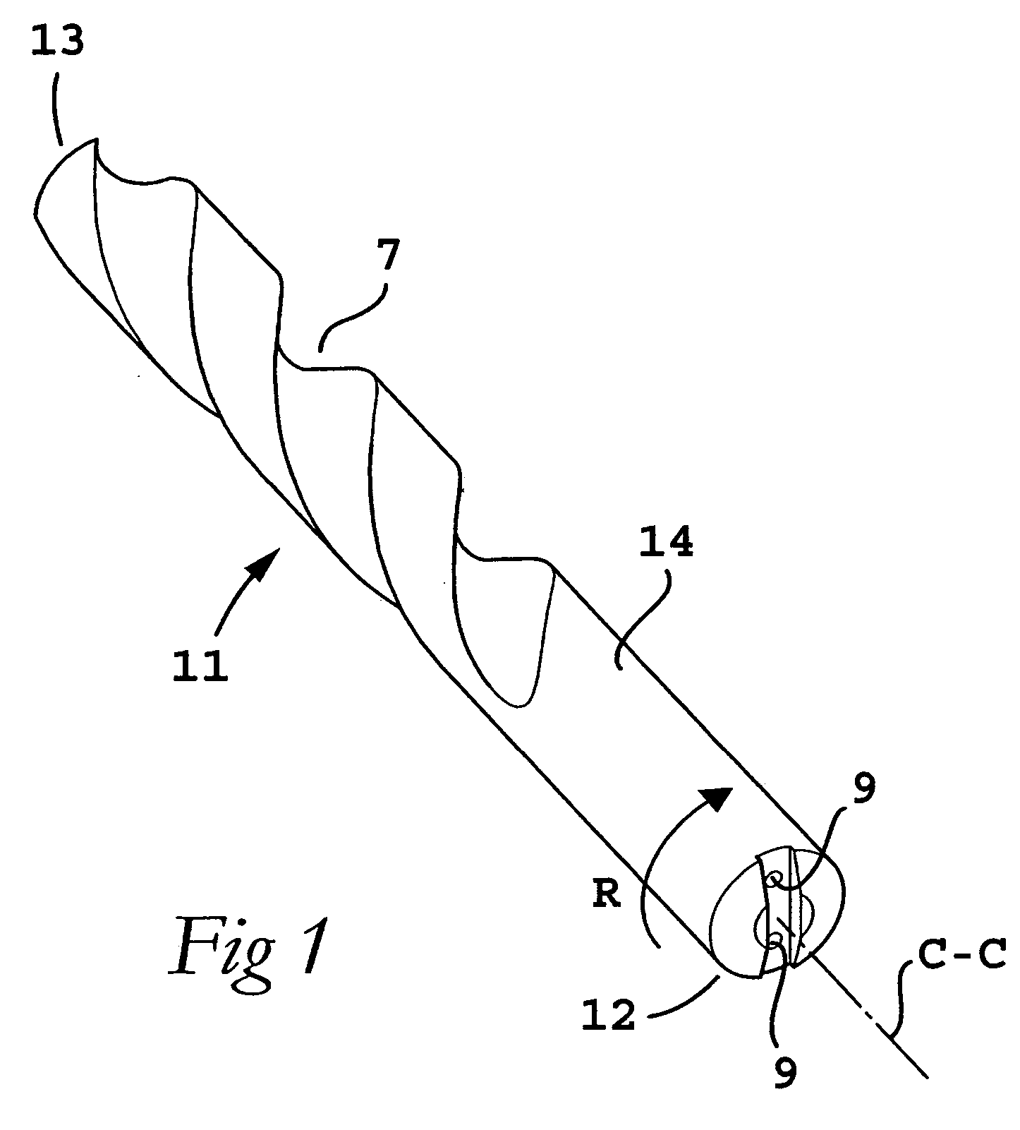
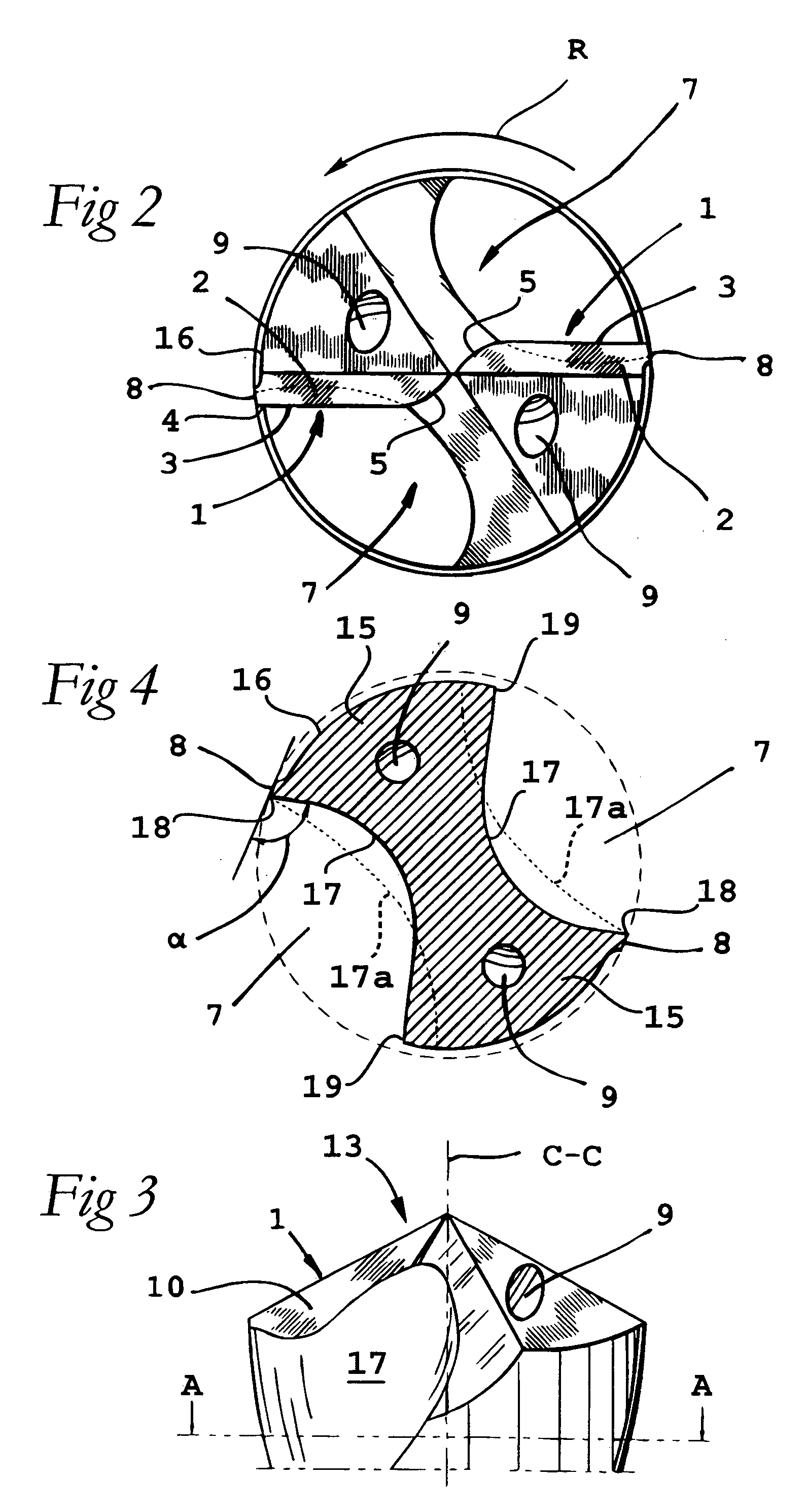
[0016]FIG. 1 illustrates the general design of a drill 11 according to an embodiment of the invention. The drill is in the form of an elongated body having a cylindrical basic shape and presenting a rearward end 12, and a front end in the form of a tip 13. A rear portion 14 of the body serves as a fastener, that can be mounted and fixed in a machine tool (not shown) for rotating the same, more specifically about a center axis C-C and in the direction of rotation R (see also FIG. 2). In an embodiment, the drill is solid, i.e., it is in its entirety manufactured from one and the same material, for instance cemented carbide, ceramics, cermet or high-speed steel.

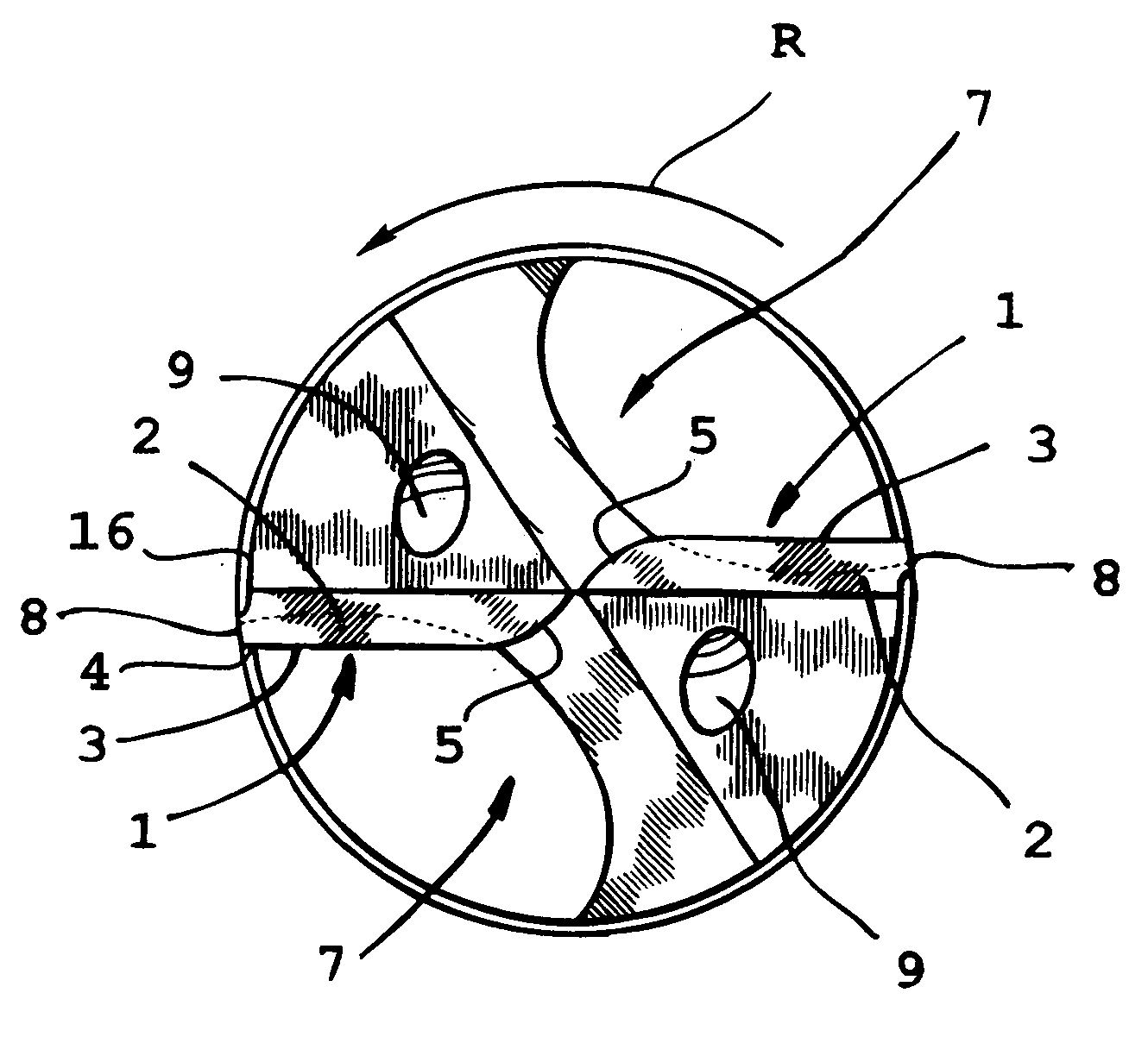
[0017] As illustrated in FIG. 2, the drill 11 includes two cutting edges generally designated 1, which are identical and include a straight portion 3 as illustrated in the end view in FIG. 2. The straight portion 3 extends from an outer end 4 at the periphery of the drill and inwards towards the center of the drill, but not thr...


PUM

PropertyMeasurementUnit
angleaaaaaaaaaa
acute angleaaaaaaaaaa
angleaaaaaaaaaa

Abstract

A drill for chip removing machining, including a front tip including at least one cutting edge and a chip flute. The chip flute is countersunk in an envelope surface of a body of the drill and extends rearwardly from the cutting edge. The chip flute is generally defined by a cross-section-wise concavely vaulted surface located between first and second longitudinal borders, the first longitudinal border extending from an area of a peripheral end of the cutting edge. The chip flute is deeper in an area of the first longitudinal border than in an area of the second longitudinal border such that a curve defining the cross-sectional shape of the flute surface has a radius of curvature that is smallest in the vicinity of the first longitudinal border and that increases towards the second longitudinal border. The flute surface transforms into a planar chip surface, which in turn transforms into the cutting edge.

Description

[0001] This application claims priority under 35 U.S.C. § 119 to Swedish Patent Application No. 0500027-8 filed on Jan. 5, 2005, the disclosure of which is incorporated by reference herein in its entirety. FIELD OF THE INVENTION [0002] The present invention relates generally to a drill for chip removing machining, including a front tip having at least one cutting edge, and a chip flute that is countersunk in an envelope surface and that extends rearwardly from the cutting edge. The flute is generally defined by a cross-section-wise concavely vaulted surface located between longitudinal borders, a first one of which extends from the area of a peripheral end of the cutting edge. BACKGROUND OF THE INVENTION [0003] As disclosed in U.S. Pat. No. 5,088,863 and U.S. Pat. No. 5,230,593, two types of drills for chip removing machining are previously known, one of the types having straight cutting edges, and the other of the types having curved cutting edges. [0004] Generally, in drills havin...

Claims


Application Information

Patent Timeline
Patent Type & Authority Applications(United States)
IPC IPC(8): B23B51/00B23BB23B51/02
CPCB23B51/02B23B2251/04Y10T408/909Y10T408/9097B23B2251/406H04N7/18G03B17/08H04N23/56H04N23/51B23B51/0002B23B2251/047
Inventor LINDBLOM, STEFAN
Owner SANDVIK INTELLECTUAL PROPERTY AB
Why Eureka
Try Eureka