
Method for preventing edge peeling defect

Inactive Publication Date: 2006-08-03
UNITED MICROELECTRONICS CORP
View PDF14 Cites 2 Cited by
  • Summary
  • Abstract
  • Description
  • Claims
  • Application Information

AI Technical Summary

Benefits of technology

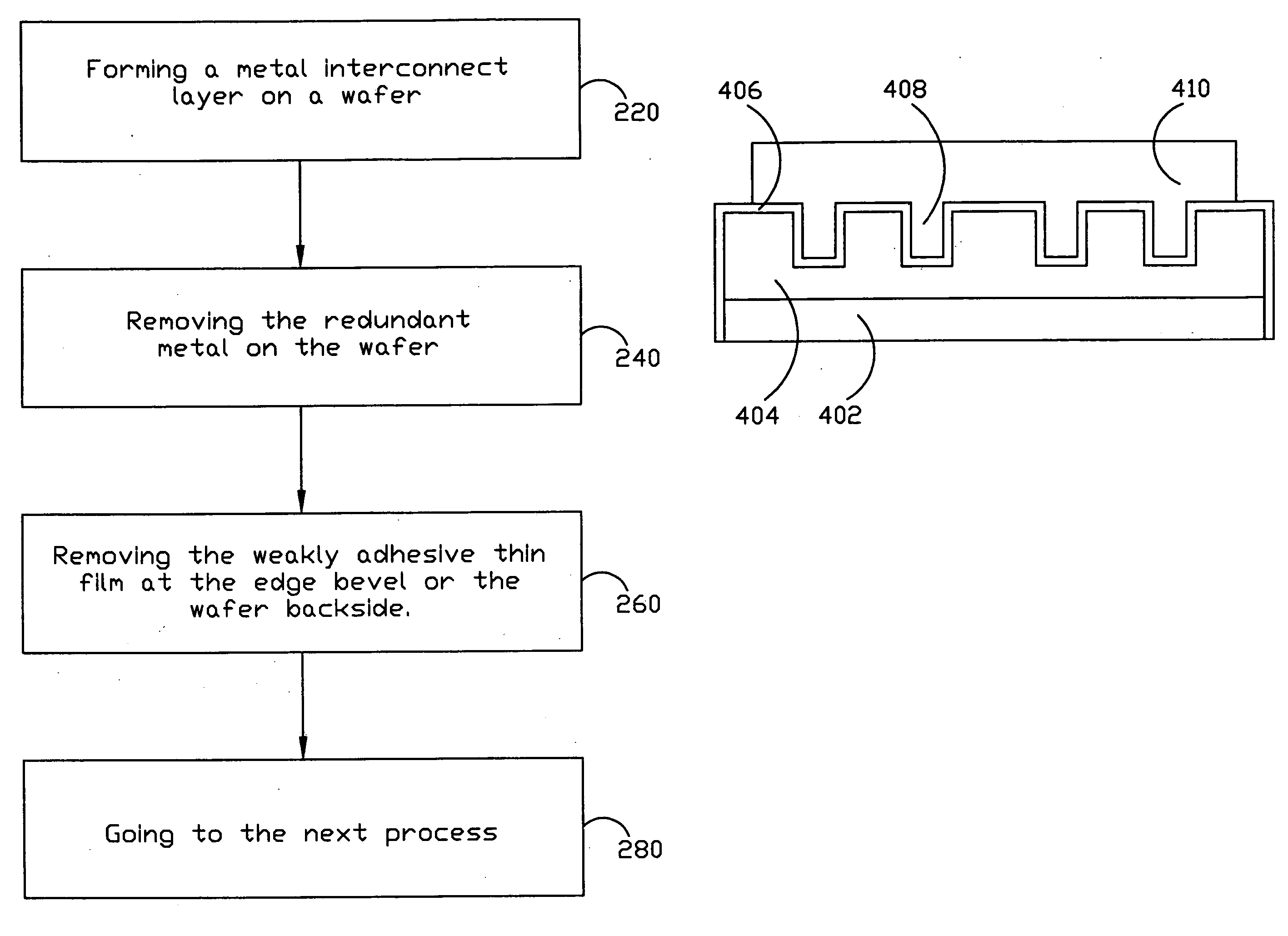
[0009] In accordance with the present invention, a method for preventing edge peeling defect is provided for preventing the peeling defects by introducing a step for removing the structure or thin film at the wafer edge in an interconnect manufacture, so that the peeling defects in the prior art can be efficiently prevented.
[0010] It is another object of this invention to raising the yield of the semiconductor manufacture by performing a step for removing the thin film at the wafer edge and at the wafer backside.
[0011] It is still another object of this present invention to decrease the pollution source of the chamber(s) of the semiconductor manufacture by performing a step for removing the thin film at the wafer edge and at the wafer backside after forming an interconnect layer on the wafer, wherein the structure may be peeling in the following process, and thus the pollution chance of the chamber(s) will be lowered by this invention.
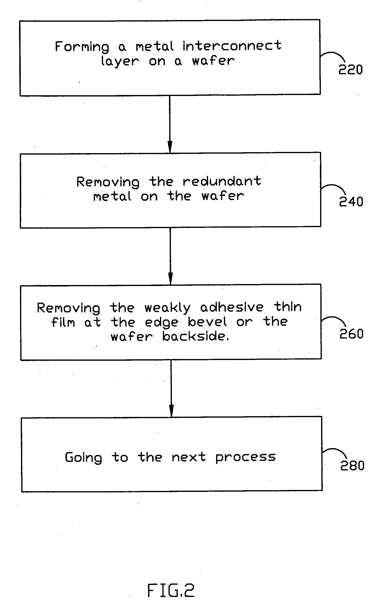
[0012] In accordance with the above-mentioned objects, the invention provides a method for preventing edge peeling defect. The above-mentioned method can be applied in an interconnect manufacture. According to this prevent invention, after forming a structure comprising an interconnect layer on a wafer, a step is introduced for removing the structure or thin film at the wafer edge, wherein the structure or thin film is not covered by the metal interconnect layer and may be peeling in the following process. The above-mentioned structure or thin film can be removed by the edge bevel removal technology, or the edge polishing technology. Therefore, according to this invention, it is efficiently for preventing the peeling defects in the prior art, and the yield of the semiconductor manufacture can be efficiently improved. Moreover, the pollution, due to the peeling fragment, of the chamber(s) of the semiconductor manufacture can be decreased by the design of this invention.

Problems solved by technology

However, because the adhesion of the barrier layer to some structure, such as the bare Si, is not good enough, the peeling of portions of the barrier layer at the wafer edge, even including the structure on the barrier layer at he wafer edge, may happen during the following process.
The above-mentioned peeling will cause many defects in the semiconductor manufacture.
If the peeling is serious, the wafer will become useless and waste.
Moreover, the chamber(s) of the semiconductor manufacture will be polluted by the above-mentioned peeling.

Method used


Image

  • Method for preventing edge peeling defect
  • Method for preventing edge peeling defect
  • Method for preventing edge peeling defect

Examples


Embodiment Construction

[0021] Some sample embodiments of the invention will now be described in greater detail. Nevertheless, it should be recognized that the present invention can be practiced in a wide range of other embodiments besides those explicitly described, and the scope of the present invention is expressly not limited except as specified in the accompanying claims.

[0022] One preferred embodiment of this invention is a method for preventing edge peeling defect. In a metal interconnect manufacturing, in order to keeping the metal diffusing into the substrate or other structure under the metal interconnect layer, a thin film is usually formed on the substrate or the structure under the metal interconnect layer to be the barrier layer before forming the metal interconnect layer. The thin film can be formed by deposition, i.e. Physical Vapor Deposition. After the metal interconnect layer is formed, the barrier layer at the edge bevel on the wafer would appear as a thin film because the removal of t...


PUM


Abstract

A method for improving edge peeling defect is disclosed in this invention. According to this invention, a wafer can be kept from the edge peeling defect of the prior art by introducing a step for removing the weakly adhesive films and the metal structures at the wafer edge after forming a metal interconnect layer on the wafer. Thus, this invention can raise the yield of semiconductor manufacturing, and reduce the pollution chance of the chamber of the semiconductor manufacture.

Description

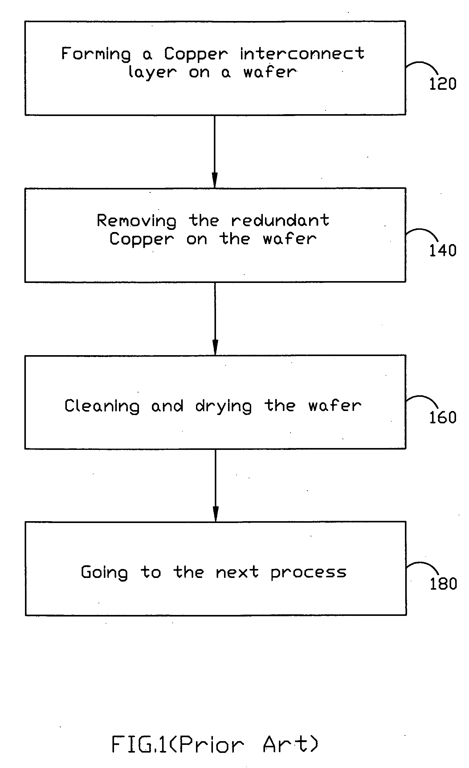
[0001] This application is a continuation in part of U.S. patent application Ser. No. 10 / 685,588, filed Oct. 16, 2003.BACKGROUND OF THE INVENTION [0002] 1. Field of the Invention [0003] This present invention relates to a semiconductor manufacturing, and more particularly, to a method for preventing the edge peeling defect after an interconnect process. [0004] 2. Description of the Prior Art [0005] Interconnect plays an important role in a semiconductor structure. For instance of copper interconnect, particularly for the semiconductor manufacture of deep sub-micron (DSM), by employing Copper interconnect process and the low-K material as the dielectric layer, the RC delay (resistance capacitance time delay) and the electro-migration effect can be reduced. [0006] For example, FIG. 1 depicts a flowchart of a copper interconnect structure in the prior art. Referring to FIG. 1, first of all, a Copper interconnect layer is formed on a wafer, as the step 120. The Copper interconnect layer...

Claims


Application Information

Patent Timeline
IPC IPC(8): H01L21/4763B24B49/00B24B51/00H01L21/02
CPCH01L21/02087H01L21/0209H01L21/76883B24B49/00B24B51/00
Inventor HSU, CHIA-LINLEE, SHU-HSIENTSAI, CHIEN-CHIENLU, HSIAO-LING
Owner UNITED MICROELECTRONICS CORP
Learn More