Method and apparatus for improving the performance of capacitive acoustic transducers using bias polarity control and multiple firings

a capacitive acoustic transducer and bias polarity control technology, applied in the field of acoustic transducers, can solve the problems of specific methods of multiple firings and combinations of such firings, as disclosed, not taught, and achieve the effect of improving its performan

Inactive Publication Date: 2006-08-03
SIEMENS MEDICAL SOLUTIONS USA INC
View PDF52 Cites 52 Cited by
  • Summary
  • Abstract
  • Description
  • Claims
  • Application Information

AI Technical Summary

Benefits of technology

[0018] The present invention provides a method of operating a bias polarity controlled microfabricated ultrasonic transducer to improve its performance in imaging non-linear media, such as in contrast agen...

Problems solved by technology

However, specific methods of multiple firings and combi...

Method used


Image

  • Method and apparatus for improving the performance of capacitive acoustic transducers using bias polarity control and multiple firings
  • Method and apparatus for improving the performance of capacitive acoustic transducers using bias polarity control and multiple firings
  • Method and apparatus for improving the performance of capacitive acoustic transducers using bias polarity control and multiple firings

Examples


Embodiment Construction

[0033] The present invention will now be described in detail with reference to the drawings, which are provided as illustrative examples of the invention so as to enable those skilled in the art to practice the invention. Notably, the figures and examples below are not meant to limit the scope of the present invention. Moreover, where certain elements of the present invention can be partially or fully implemented using known components, only those portions of such known components that are necessary for an understanding of the present invention will be described, and detailed descriptions of other portions of such known components will be omitted so as not to obscure the invention. Further, the present invention encompasses present and future known equivalents to the known components referred to herein by way of illustration.

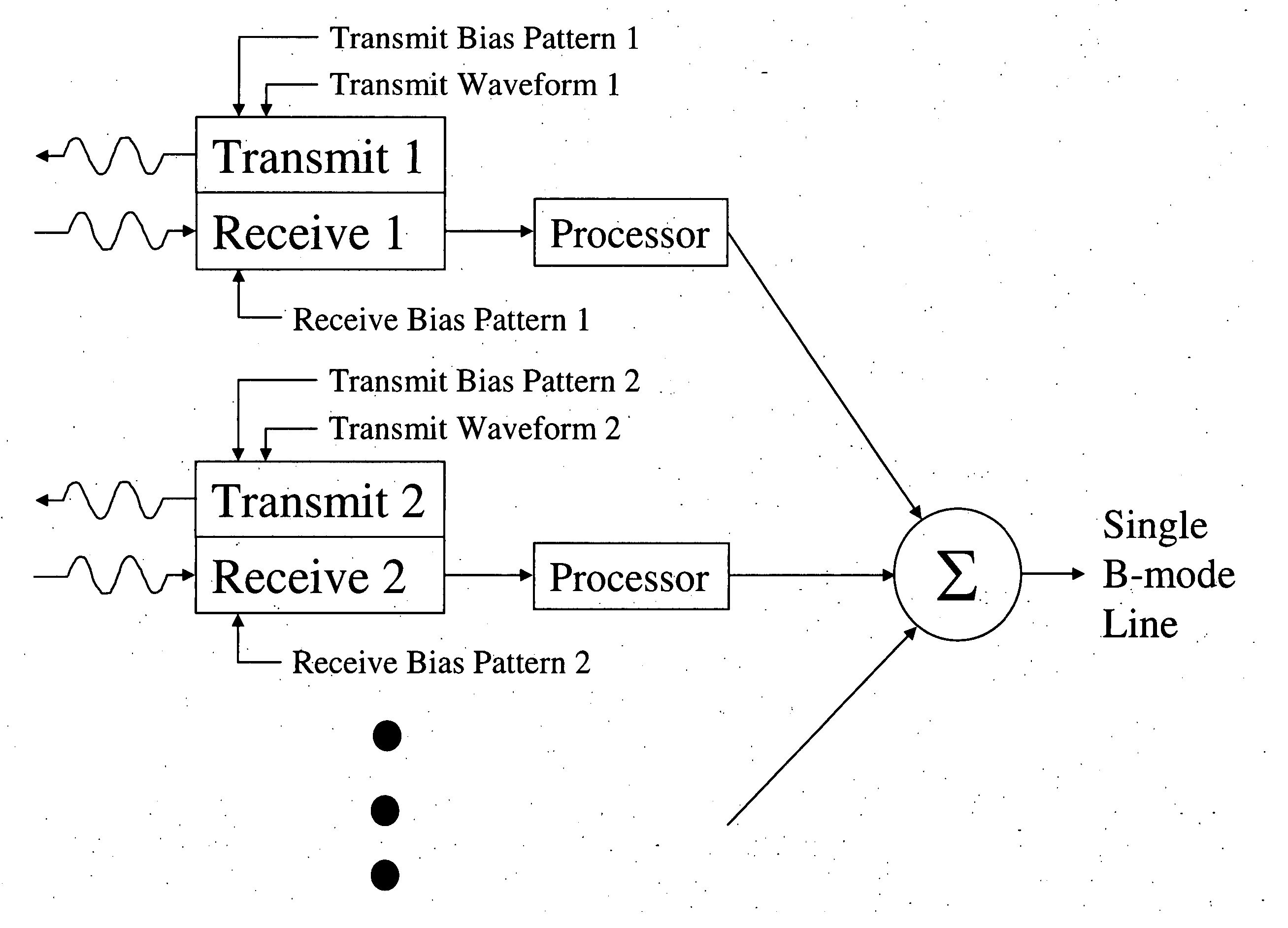
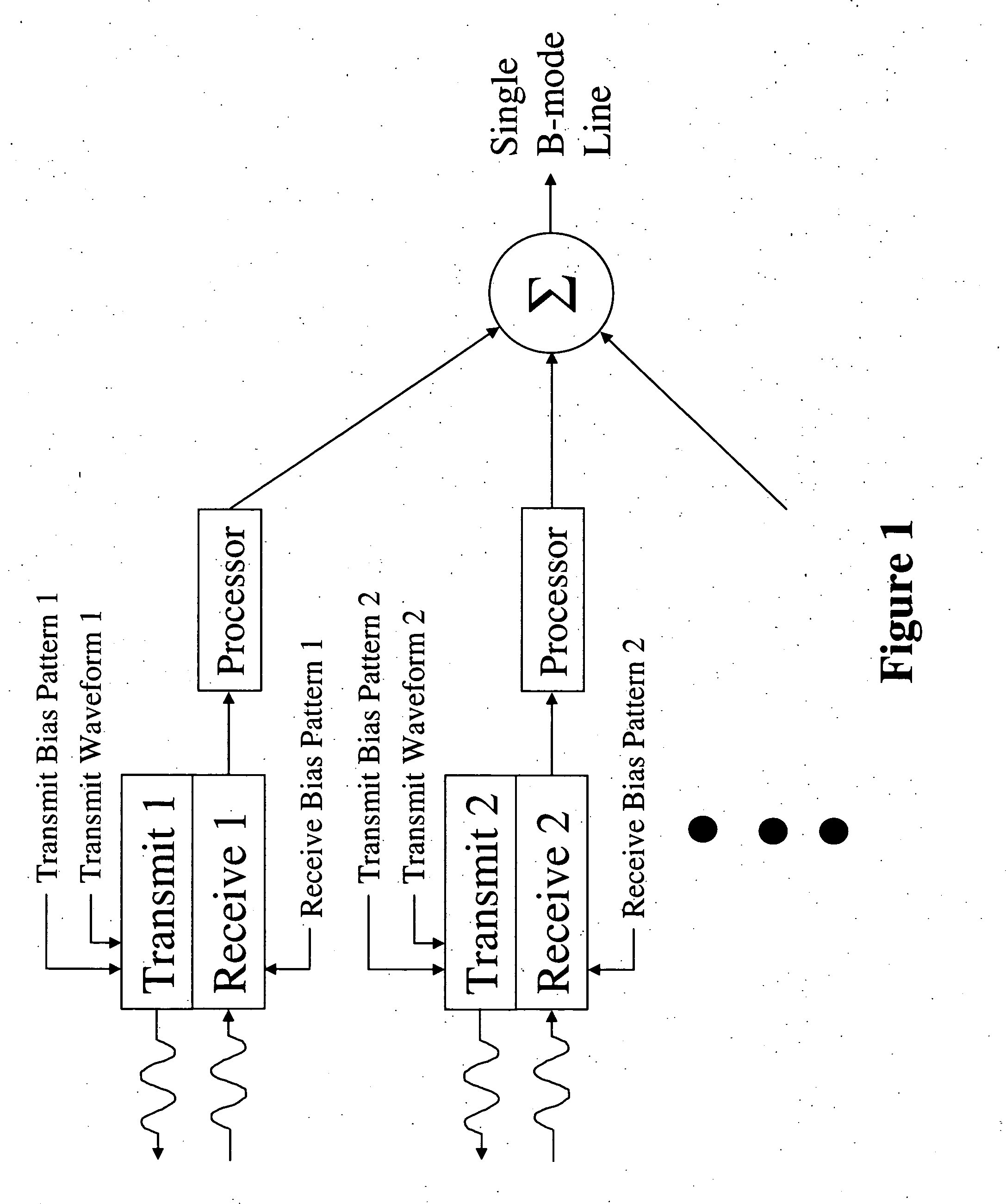
[0034] The present invention relates to capacitive microfabricated ultrasonic transducer (cMUT) arrays with bias voltage control. FIG. 1 illustrates the concep...


PUM


Abstract

Presented is a method of operating a capacitive microfabricated ultrasonic transducer (cMUT) array with multiple firings of varying bias voltage polarity patterns to improve its performance in imaging non-linear media, such as in contrast agent imaging or tissue harmonic imaging. Additionally, transducers incorporating the method are provided. The method of cMUT operation and the corresponding cMUT does not require pre-distortion or phase inversion of the transmit signal and can achieve an improvement in the elevation focus of the cMUT, as compared to the elevation focus that a single firing can achieve. Further, the method of operating the cMUT minimizes the deleterious effects that result from insulators being subjected to high electric fields.

Description

CROSS-REFERENCE TO RELATED APPLICATIONS [0001] The present application is a continuation-in-part of, and claims the benefit of priority under 35 U.S.C. § 120 from, commonly assigned U.S. patent application Ser. No. 10 / 367,106 to Daft et al. filed on Feb. 14, 2003 and entitled “Microfabricated Ultrasonic Transducers with Bias Polarity Beam Profile Control and Method of Operating the Same,” which is hereby incorporated by reference in its entirety and for all purposes. [0002] The present application additionally claims the benefit of priority under 35 U.S.C. § 119(e) from U.S. Provisional Patent Application No. 60 / 460,638 to Panda et al. filed on Apr. 4, 2003 and entitled “Method and Apparatus for Improving the Performance of Capacitive Acoustic Transducers using Bias Polarity Control and Multiple Firings,” which is hereby incorporated by reference in its entirety and for all purposes.FIELD OF THE INVENTION [0003] Generally, the present invention relates to the field of acoustic trans...

Claims


Application Information

Patent Timeline
IPC IPC(8): A61B8/06A61B8/14
CPCB06B1/0292G01S7/52038G01S7/52047G01S15/8995G01S15/8909G01S15/8959G01S7/52077
Inventor PANDA, SATCHIWAGNER, PAUL A.DAFT, CHRISTOPHER M.LADABAUM, IGAL
Owner SIEMENS MEDICAL SOLUTIONS USA INC
Why Eureka
Try Eureka