Air quality monitoring systems and methods

a monitoring system and air quality technology, applied in the direction of static/dynamic balance measurement, instruments, heating types, etc., can solve the problems of asthma incidence rate, aggravate the air quality problem, and inacceptable indoor air quality, and achieve the effect of increasing the scor

a monitoring system and air quality technology, applied in the direction of static/dynamic balance measurement, instruments, heating types, etc., can solve the problems of asthma incidence rate, aggravate the air quality problem, and inacceptable indoor air quality, and achieve the effect of increasing the scor

US20060173580A1Inactive Publication Date: 2006-08-03AIRCUITY

Image

  • Air quality monitoring systems and methods
  • Air quality monitoring systems and methods
  • Air quality monitoring systems and methods

Examples


Embodiment Construction

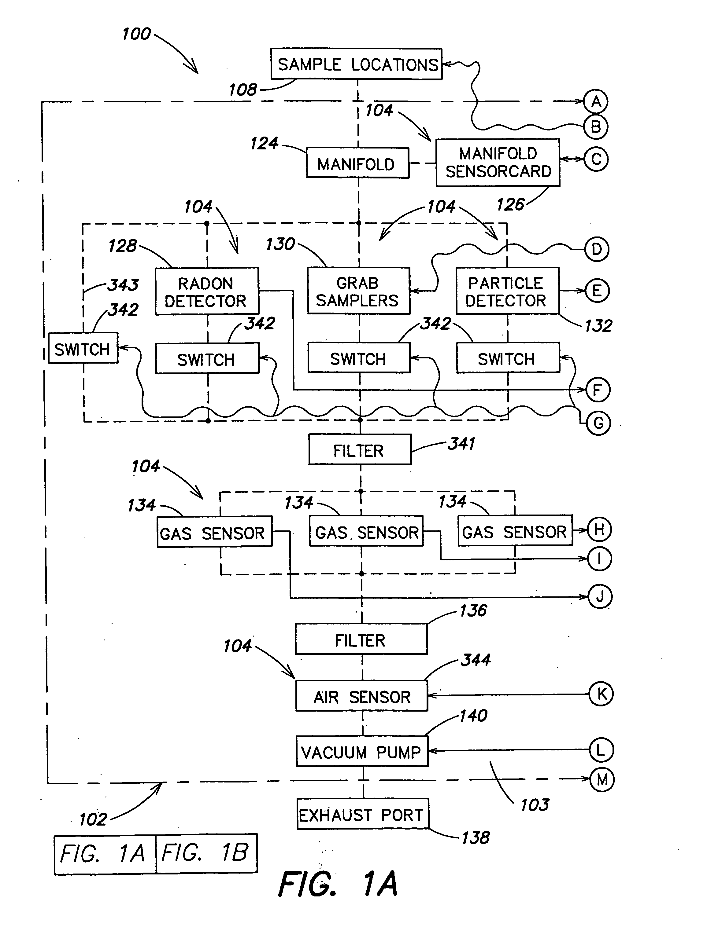
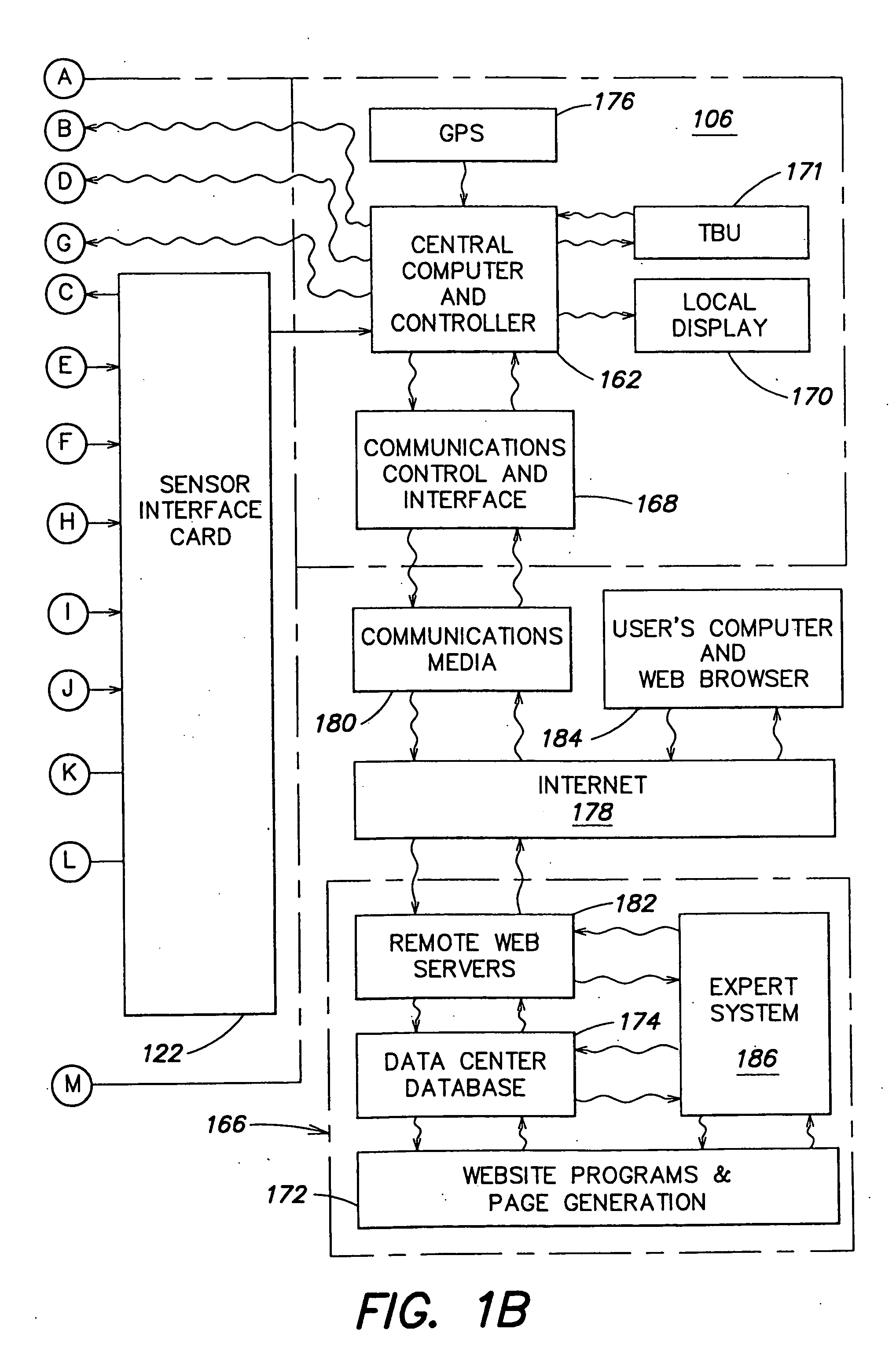
[0043] Referring to FIG. 1, a schematic block diagram of one embodiment of an air monitoring system 100 according to the present invention is shown. The air monitoring system may be a portable or an installed system, or a system having a combination of portable and installed components. The air monitoring system 100 includes an air monitoring unit 102. In a portable system, the air monitoring unit 102 may be hand held or reasonably portable. The air monitoring unit includes a sensor unit 103 having at least one sensor 104 and a control unit 106. In a portable system the air to be sampled, or sample locations 108, may be taken from the area immediately surrounding the air monitoring unit or through a tube (not shown) from one or more remote sample locations.

[0044] An installed system may have many different configurations. The installed system may include an air monitoring unit 102 installed in a building to monitor one or more spaces within the building. Referring to FIG. 2, the in...


PUM

PropertyMeasurementUnit
sizeaaaaaaaaaa
sizeaaaaaaaaaa
area indexaaaaaaaaaa

Abstract

An air monitoring system is disclosed having an air monitoring unit with at least one sensor for measuring data of an air quality parameter and a computer for storing the air quality parameter data received from the sensor. The air monitoring unit may use an installed or a portable system, or a combination of both, for measuring the air quality parameters of interest. A remote data center may be provided, and the data may be uploaded to the data center from the unit by a communications media such as the Internet. Information or instructions may also be downloaded from the data center to the unit via the communications media for controlling or modifying the function of the unit. An expert system may be provided with the air monitoring system for controlling the unit. The information or instructions downloaded to the unit may be generated by the expert system.

Description

CROSS REFERENCE TO RELATED APPLICATION [0001] This application is a divisional from U.S. Nonprovisional application Ser. No. 09 / 779,379, filed on Feb. 7, 2001 from which this divisional claims the benefit of priority.FIELD OF THE INVENTION [0002] This invention relates to air quality monitoring systems and methods. More particularly, this invention relates to an air monitoring system that is customized for a specific structure, such as a building or a home, and / or the occupants. Still more particularly, the air monitoring system measures certain air quality parameters and may provide an analysis of the data collected and may make recommendations for improving the air quality parameters. BACKGROUND OF THE INVENTION [0003] Over time people have become more energy-conscious. Because of this, the construction industry started building structures that are far “tighter” than their predecessors, with respect to air leakage. Buildings are now carefully designed to provide occupants with a p...

Claims


Application Information

Patent Timeline
03 Aug 2006
Publication
US20060173580A1
IPC
G01N33/00; G01N27/12; F24F11/02; G01N1/22; G01N1/24; G01N1/26; G01N15/06; G01N27/00
CPC
G01N1/2273; G01N1/24; G01N1/26; G01N33/0034; G01N33/0075; G01N2001/021; E05Y2800/22; Y10S706/93
Inventors
DESROCHERS, ERIC M.; SHARP, GORDON P.