Device for surface blasting component

a technology of surface blasting and components, which is applied in the direction of manufacturing tools, forging/pressing/hammering apparatus, mechanical equipment, etc., can solve the problems of significant surface roughening on the blasted surface, insufficient quality, and the rise of integrally bladed gas turbine rotors, etc., to improve the effect of machining quality, increase the effectiveness of surface blasting, and high intensity

Active Publication Date: 2006-08-10
MTU AERO ENGINES GMBH
View PDF26 Cites 16 Cited by
  • Summary
  • Abstract
  • Description
  • Claims
  • Application Information

AI Technical Summary

Benefits of technology

[0008] With a device for surface blasting components according to an example embodiment of the present invention, it may be possible to achieve an improved machining quality on the component surfaces to be machined compared to conventional devices. Furthermore, a device according to an example embodiment of the present invention may allow, for example, for a machining of blade roots or even of the blades of gas turbine blades such that sections to be hardened are simultaneously blasted from two opposite sides. On the one hand, this may increase the effectiveness in surface blasting, while on the other hand, e.g., in the case of thin-walled components, may avoid unacceptable deformations of the thin-walled component sections to be blasted. A device according to an example embodiment of the present invention may allow for the high intensity bombardment even of thin-walled disks having so-called wings on integrally bladed gas turbine rotors in ultrasonic shot blasting, without unacceptably deforming these complexly formed components in surface blasting.

Problems solved by technology

A similar problem may arise with respect to integrally bladed gas turbine rotors, which are hardened in the region of their rotor discs so as to minimize the wear rate.
In conventional shot blasting, a significant surface roughening may occur on the blasted surfaces.
In this manner, it is possible to achieve only an insufficient quality in shot blasting the profiled bearing surfaces of the blade roots.
Furthermore, using the device described in U.S. Pat. No. 6,536,109, it may not be possible to blast thin-walled components, since such thin-walled components may be exposed to unacceptable deformation when machined in this device.

Method used


Image

  • Device for surface blasting component
  • Device for surface blasting component
  • Device for surface blasting component

Examples


Embodiment Construction

[0037] Example embodiments of the present invention are described in greater detail with reference to FIGS. 1 to 5.

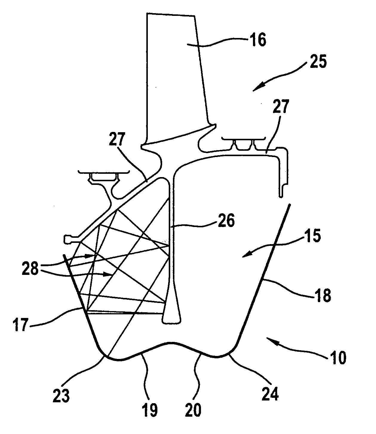
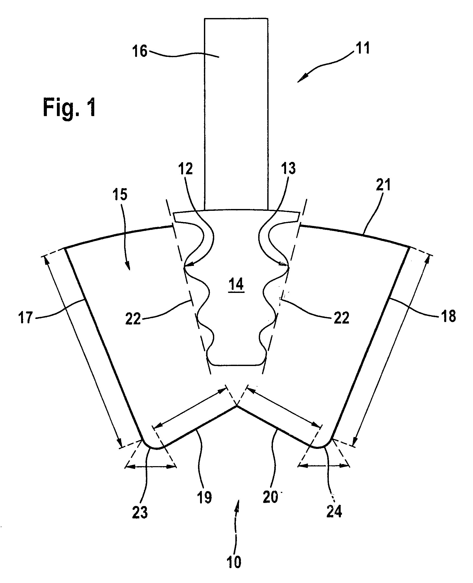
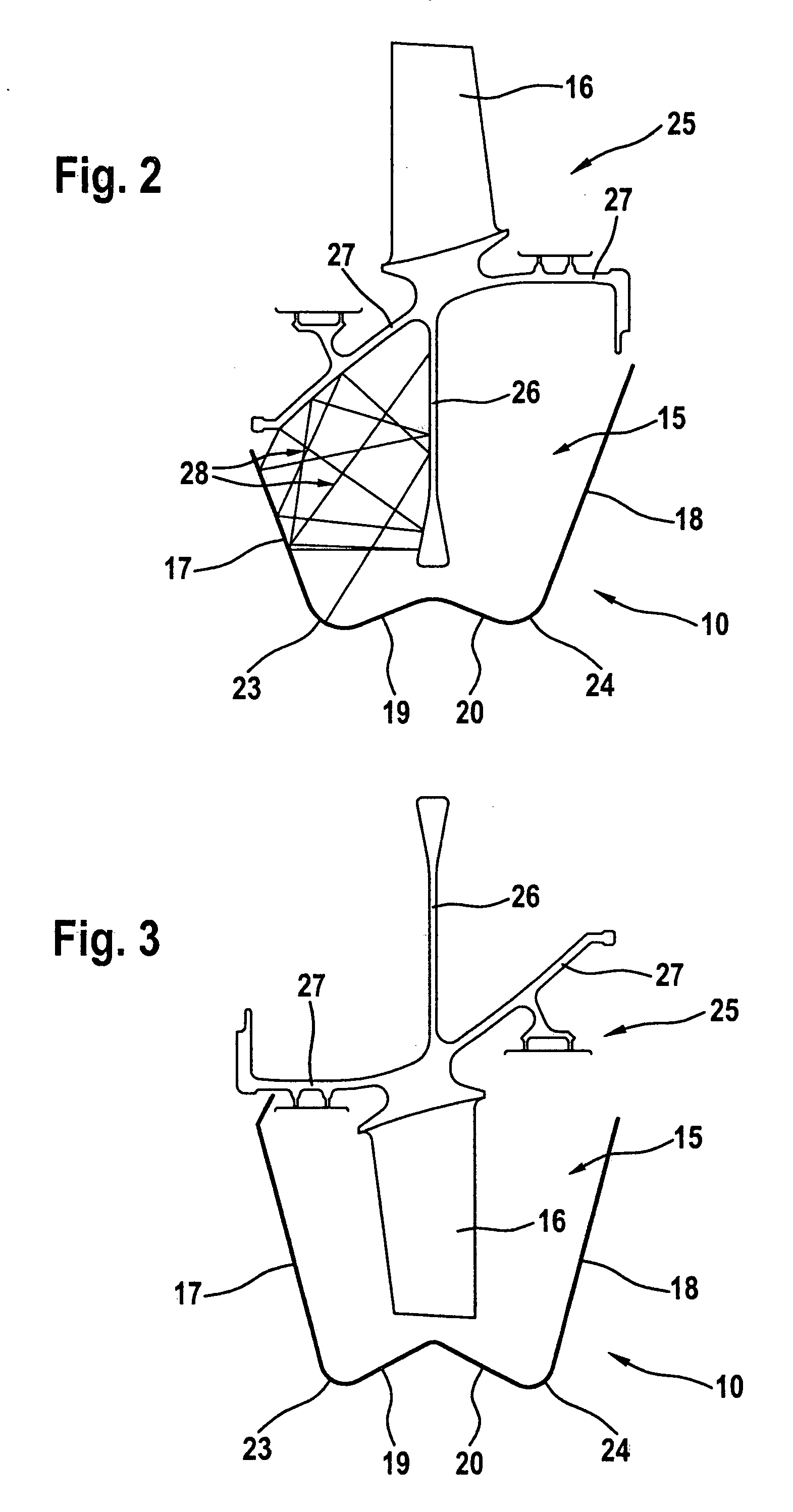
[0038]FIG. 1 is a schematic view of a device 10 for ultrasonic shot blasting together with a gas turbine blade 11, which in device 10 is to be blasted at profiled bearing flanks or bearing surfaces 12 and 13 of a blade root 14. As illustrated in FIG. 1, for this purpose, blade root 14 of gas turbine blade 11 extends into a machining chamber 15 provided by the device, a blade 16 of gas turbine blade 11, which is not to be machined in FIG. 1, projecting out of machining chamber 15 of device 10.

[0039] In the exemplary embodiment illustrated in FIG. 1, machining chamber 15 is W-shaped in its cross-section or characterized by a W-profile. Thus, cross-sectionally W-shaped machining chamber 15 is bounded by two outer, substantially vertical long sides 17 and 18 as well as by two inner, substantially horizontal short sides 19 and 20. Each of these sides 17, 18, 19 and 20 is f...


PUM

PropertyMeasurementUnit
wear rateaaaaaaaaaa
gravityaaaaaaaaaa
timeaaaaaaaaaa

Abstract

A device for surface blasting, e.g., for ultrasonic shot blasting, components, e.g., gas turbine components, includes at least one vibrator having an oscillating surface, e.g., having at least one ultrasonic sonotrode, the or each oscillating surface of the or each vibrator being adjoined by a machining chamber for receiving a section to be blasted of the component to be machined. The machining chamber is bounded in its cross-section by at least three sides, e.g., by at least two substantially vertical sides and by at least one substantially horizontal side. At least the substantially vertical sides of the machining chamber are formed by oscillating surfaces of in each case one vibrator.

Description

CROSS-REFERENCE TO RELATED APPLICATIONS [0001] The present application claims priority to Application No. 10 2004 037 954.8, filed in the Federal Republic of Germany on Aug. 5, 2004, which is expressly incorporated herein in its entirety by reference thereto. FIELD OF THE INVENTION [0002] The present invention relates to a device for surface blasting, e.g., for ultrasonic shot blasting, components, e.g., gas turbine components. BACKGROUND INFORMATION [0003] Gas turbines, particularly aircraft engines, have at least one rotor equipped with rotating moving blades, particularly in the region of a compressor and of a turbine, the rotating moving blades of the gas turbine being either anchored by profiled blade roots in recesses of the gas turbine rotor or being an integral part of a gas turbine rotor. If the moving blades are anchored by blade roots in corresponding recesses of the rotor, then the blade roots are profiled either according to the so-called fir tree design or according to...

Claims


Application Information

Patent Timeline
Patent Type & Authority Applications(United States)
IPC IPC(8): B23P15/04C21D7/06
CPCB24C1/10B24C5/005B24C5/08Y10S72/71Y10T29/4932Y10T29/49336Y10S451/91Y10T29/479
Inventor BAYER, ERWINDAUTL, THOMASPESCHKE, THOMASPOLANETZKI, HOLGER
Owner MTU AERO ENGINES GMBH
Why Eureka
Try Eureka