Rapidly-deployable lightweight load resisting arch system

a lightweight, load-resisting technology, applied in mining structures, tunnels, foundation engineering, etc., can solve the problems of high cost of precast concrete structures, heavy precast concrete structures, and heavy equipment on site, and achieves high cost and time-consuming. , the effect of increasing the cost of precast concr

a lightweight, load-resisting technology, applied in mining structures, tunnels, foundation engineering, etc., can solve the problems of high cost of precast concrete structures, heavy precast concrete structures, and heavy equipment on site, and achieves high cost and time-consuming. , the effect of increasing the cost of precast concr

US20060174549A1Active Publication Date: 2006-08-10UNIVERSITY OF MAINE

Image

  • Rapidly-deployable lightweight load resisting arch system
  • Rapidly-deployable lightweight load resisting arch system
  • Rapidly-deployable lightweight load resisting arch system

Examples


examples

Analysis and Design

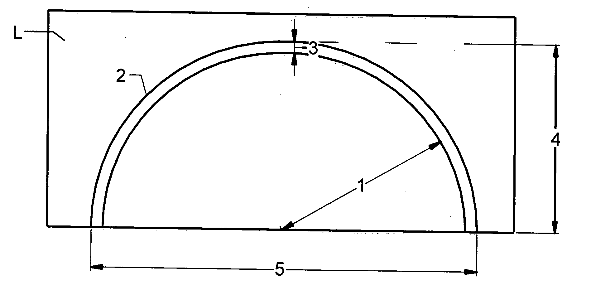
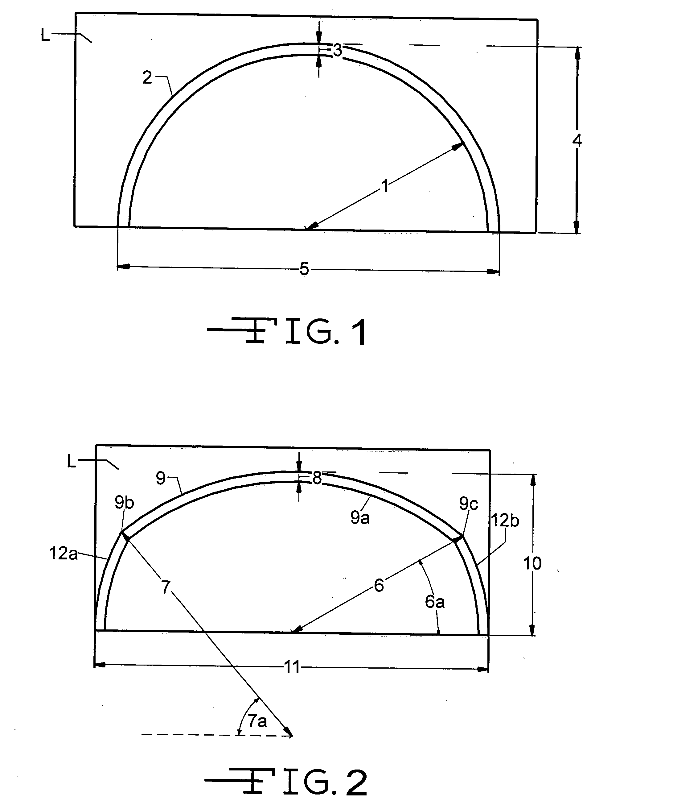
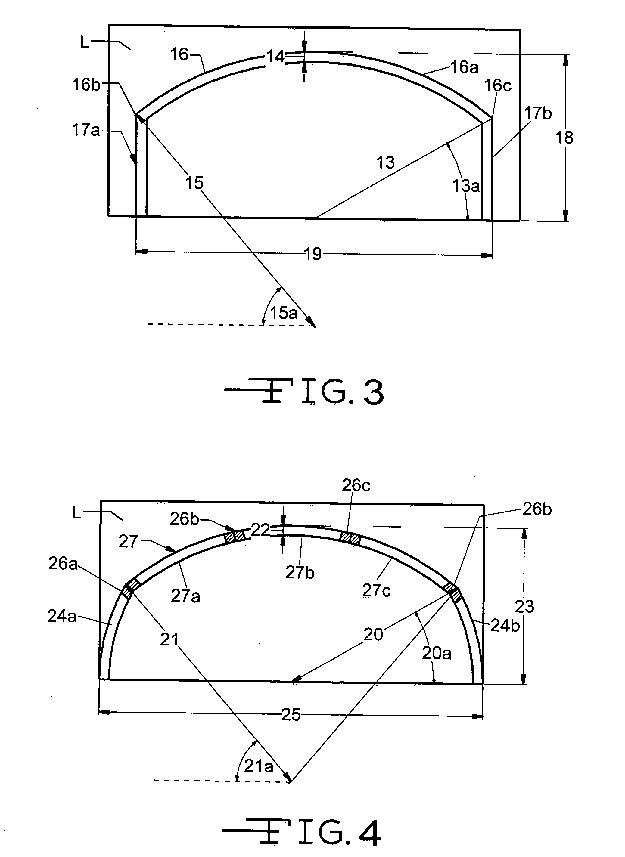
[0069] In one example, the arch tubes of this invention are designed, by illustrating the design of 15 ft (4.6 m), 7 in. (178 mm) concrete-filled FRP arch tube, under the following conditions: [0070] 1. The empty FRP arch tube is checked against dead load stresses developed by the weight of wet concrete. [0071] 2. Calculation of maximum concentrated vertical load at midspan, which requires an iterative analysis. A moment-curvature numerical model is used to calculate the ultimate moment capacity of the 7 in. (178 mm) diameter FRP-concrete composite section. The critical concentrated applied loads required to achieve this ultimate moment are determined using a conventional structural analysis model. [0072] 3. Global buckling is checked under two cases: [0073] a. Prior to the curing of concrete [0074] b. After curing of concrete and application of the concentrated load at midspan.

[0075] Local wall buckling is also checked.

1. Check FRP Arch Tubes under Weight of ...


PUM


Abstract

A rapidly-erectable lightweight load resisting system for the construction of buried arched bridges, tunnels or underground bunkers, has a plurality of lightweight arched tubular support members which are formed of a fiber reinforced polymer material and are substantially oriented in a vertical plane. The lightweight tubular support members are connected by at least one or more lateral force resisting members which are positioned in a direction perpendicular to the vertical plane of the tubular support members, and which are capable of transferring vertical loads to the tubular support members and of providing lateral-load capacity to the load resisting system. The tubular support members are fitted with one or more holes near the top which allows them to be filled with a suitable material to provide additional strength or stiffness.

Description

BACKGROUND OF THE INVENTION [0001] This invention relates in general to a rapidly-deployable lightweight tubular arch load resisting system capable of resisting loads both in the vertical and horizontal directions, useful for the rapid construction of buried arched bridges, tunnels, underground storage facilities, hangers, or bunkers, which minimizes the need for heavy construction equipment at the site. [0002] In the past, there have been several types of technologies that have been used in order to construct short and medium span buried arch bridges, as well as some underground storage facilities and tunnels. These structures are typically covered with a soil overburden which receives traffic or other loading. [0003] One technology includes the use of precast concrete structures which are made in one location and then shipped to the construction site. While the precast concrete structures are made skillfully and meet the construction requirements, the use of precast concrete struc...

Claims


Application Information

Patent Timeline
10 Aug 2006
Publication
US20060174549A1
IPC
E04B1/32
CPC
E02D29/05; E04B1/168; E21D15/483; E21D11/10; E21D11/18; E04B1/3205
Inventors
DAGHER, HABIB J.; LANDIS, ERIC N.