Forming apparatus for precambered metal sections

a technology of metal sections and forming apparatus, which is applied in the direction of metal rolling arrangement, metal working apparatus, manufacturing tools, etc., can solve the problems of difficult to incorporate precamber into metal sections, and achieve the effect of easy introduction

Inactive Publication Date: 2006-08-10
BLUESCOPE STEEL LTD
View PDF9 Cites 5 Cited by
  • Summary
  • Abstract
  • Description
  • Claims
  • Application Information

AI Technical Summary

Benefits of technology

[0009] An advantage of the present invention is that the profile and precamber can be introduced into the section in a single pass. Furthermore, the method can be easily introduced into an existing roll forming line merely by including additional processing stations.
[0010] The applicants have found that by preconditioning the metal strip through differential prestretching, the amount that the metal section can be bent without buckling of the section, or introducing significant areas of weakness in the metal section, can be significantly increased.
[0011] In one form, the metal strip is differentially stretched continuously in a longitudinal direction of the metal strip, so as to produce longitudinally extending elongated portions in the metal strip.
[0012] In one form, the differential stretching is designed at least in part to compensate for the tendency of some parts of the metal section to sh

Problems solved by technology

Whilst metal decking according to the above form has improved performance, difficu

Method used


Image

  • Forming apparatus for precambered metal sections
  • Forming apparatus for precambered metal sections
  • Forming apparatus for precambered metal sections

Examples


Embodiment Construction

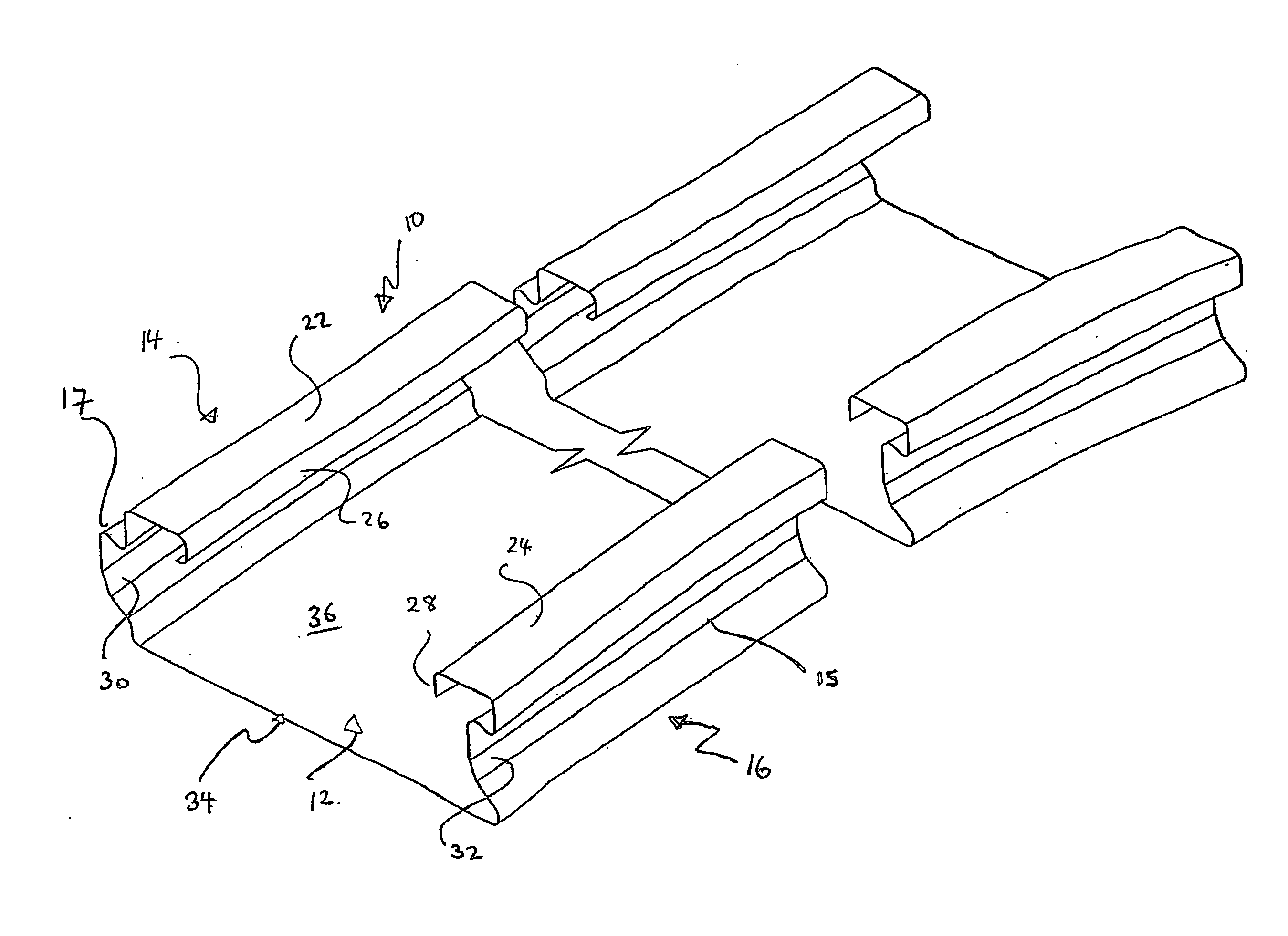
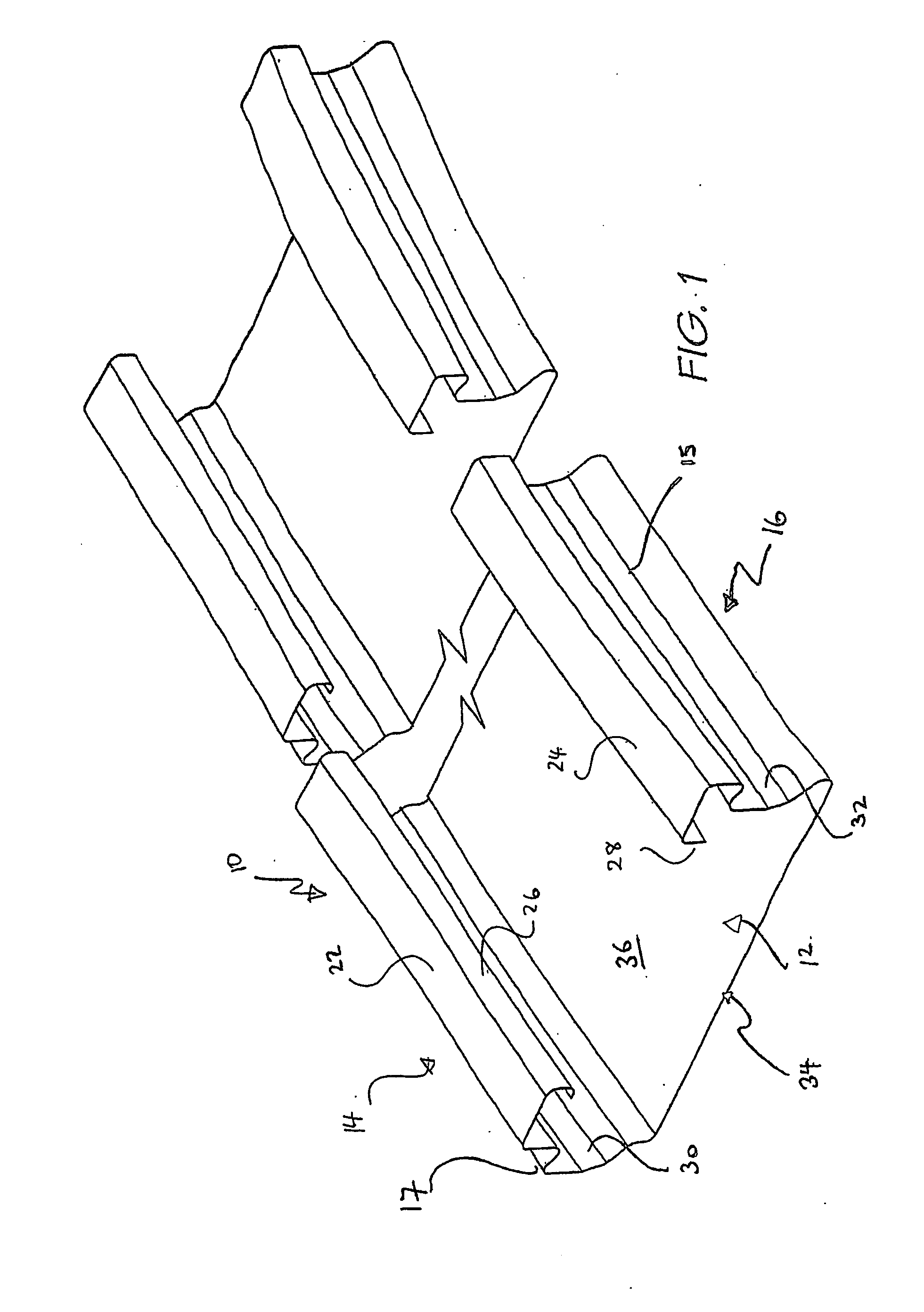
[0035] As shown in FIG. 1, a metal decking 10 is disclosed which is elongate and of generally C-section profile including a pan 12 and a pair of upstanding edge margins 14, 16 respectively. The metal decking member 10 in use is interconnected with a like member so as to form metal decking. The metal decking is designed with edge margins of one sheet abutting the other edge margins of an adjacently laid sheet and a concrete slab is cast onto the decking which embeds the upstanding edge margins 14 and 16.

[0036] Each of the upstanding edge margins 14 and 16 include webs 15, 17 that extend upwardly from the pan 12. Flanges 22,24 extend inwardly from an upper end of respective ones of the webs 15, 17 and includes a respective lip return 26, 28. One lip return 26 is turned back towards its web 15, whereas the other lip return 28 is disposed generally parallel to its web 17.

[0037] The web 15, 17 of edge margins 14 and 16 each include a respective longitudinally extending rib (30, 32). Th...


PUM

PropertyMeasurementUnit
Lengthaaaaaaaaaa
Heightaaaaaaaaaa
Bending strengthaaaaaaaaaa

Abstract

A forming apparatus (50) includes a roll former (51) operative to roll form a metal strip (100) to form a profiled metal section (10) of generally C section profile including a pan (12) and a pair of upstanding edge margins (14 and 16). The section profile incorporates a longitudinal precamber which is introduced by the forming apparatus by incorporating a prestretching apparatus (52) upstream from the roll former (51), and a bending apparatus (53) located downstream of the roll former (51). The prestretching apparatus differentially stretches the metal strip (100) in its longitudinal direction so as to form portions (101, 102), which are more elongated than a laterally adjacent portion (103) of the strip (100). The differential stretching compensates for longitudinal shortening of the metal strip in forming the profiled section in the roll former (51). The bending apparatus (53) uses a (3) point bending process and includes a reaction stage (60), a fulcrum stage (61), and an action stage (62). The action stage (62) which induces loading onto the profiled section (10) so as to bend the section about the fulcrum stage (61) is incorporated with the shearing assembly. A method of forming a metal section from sheet metal strip is also disclosed. In a further aspect a shearing assembly is disclosed which is height adjustable and which also includes a cutting element (77) and shearing block (78) which are pivotally mounted to an assembly frame (74).

Description

TECHNICAL FIELD [0001] The present invention relates to an apparatus for and method of, forming a metal section from sheet metal strip. The invention has been developed especially for roll forming metal profiles such as metal decking and the invention is herein described in that context. The invention however has broader application and is not limited to that particular use. BACKGROUND OF THE INVENTION [0002] Composite structures formed from metal decking on which a concrete slab is cast are commonly used in building. Typically, the decking is installed on site so as to span supporting elements, such as columns or walls. The decking includes a pan section and upstanding edge regions which are in abutting relationship so as to form a continuous surface. Concrete is cast over the surface so that the upstanding edges are embedded in the slab. The metal decking therefore acts both as formwork for casting of the slab, and also provides tensile strength to the structure on curing of the s...

Claims


Application Information

Patent Timeline
IPC IPC(8): B21B15/00B21D5/08B21D7/08B23D15/04B23D35/00
CPCB21D5/08B21D7/08B23D15/04B23D35/005Y10T83/9447
Inventor WHITE, MERRICK
Owner BLUESCOPE STEEL LTD
Why Eureka
Try Eureka