Method for mounting a drive shaft of a compressor

a technology of compressors and drive shafts, applied in the direction of engine lubrication, electrical apparatus, dynamo-electric machines, etc., can solve the problems of increasing energy consumption, increasing the energy consumption of the motor, and requiring relatively heavy wear on the bearings, so as to simplify the manufacturing process

Inactive Publication Date: 2006-08-10
DANFOSS COMPRESSORS
View PDF6 Cites 0 Cited by
  • Summary
  • Abstract
  • Description
  • Claims
  • Application Information

AI Technical Summary

Benefits of technology

[0016] Preferably, a bearing support is used, whose opening has short measure in relation to the bearing, the opening being extended to the measure of the bearing. When using a punch, this has the advantage that after fixing the bearing support only a fine punch step is required to bring the opening to the final measure. This further simplifies the manufacturing process, as only little material has to be removed, which means that the forces required to manufacture the final opening are smaller.

Problems solved by technology

As, however, refrigerant compressors are practically operating all the year round, the energy consumption of the motor, which is required for driving the compressor unit, must be kept as small as possible.
A “leaning” drive shaft will eventually cause relatively heavy wear on the bearings.
Further, an insufficient alignment causes frictional losses in the bearings, which again cause increased energy consumption.

Method used


Image

  • Method for mounting a drive shaft of a compressor
  • Method for mounting a drive shaft of a compressor
  • Method for mounting a drive shaft of a compressor

Examples


Embodiment Construction

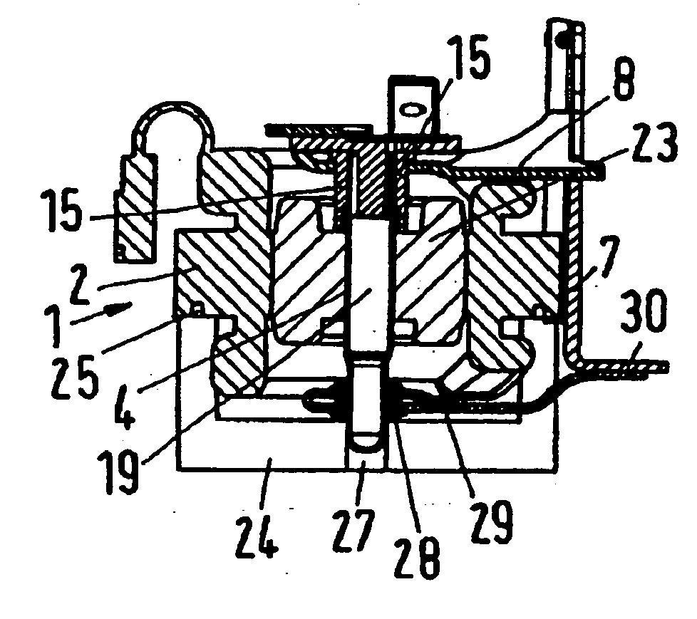
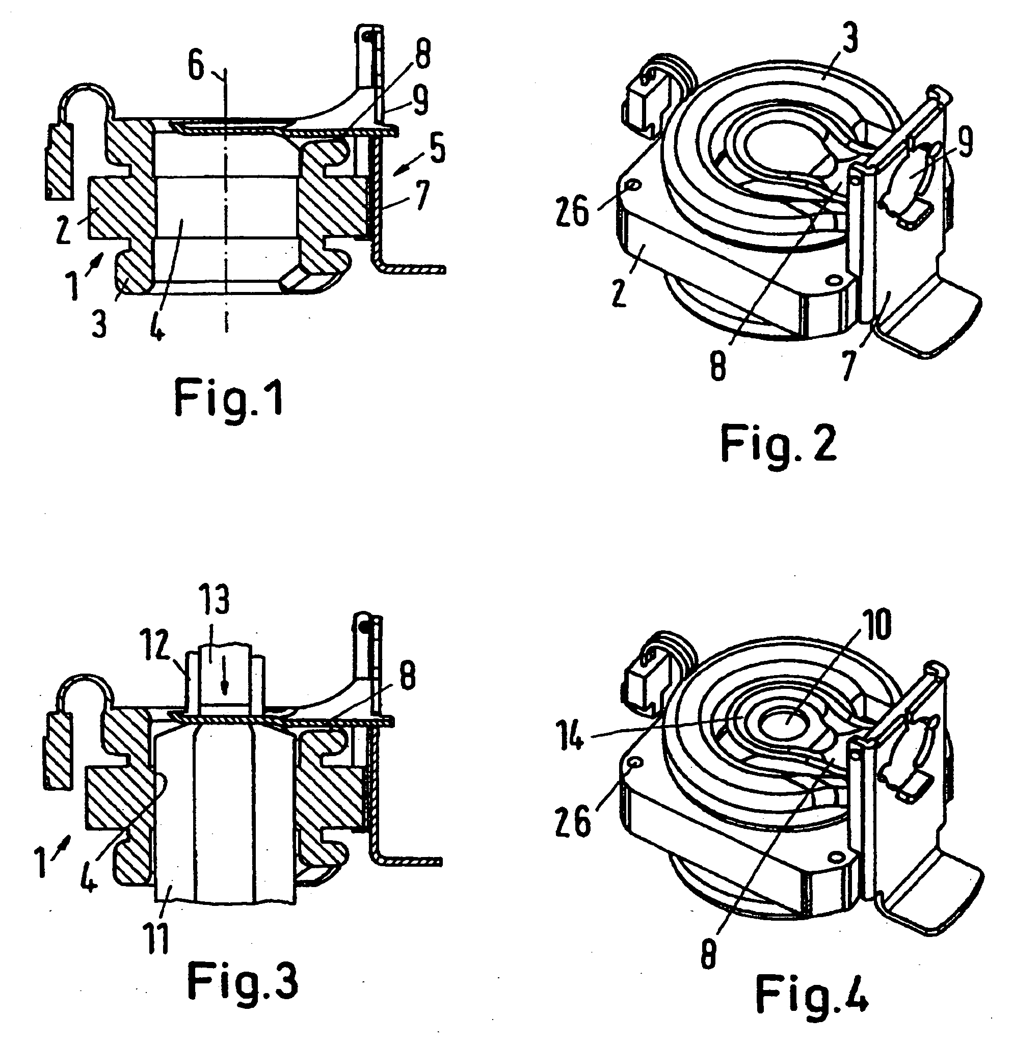
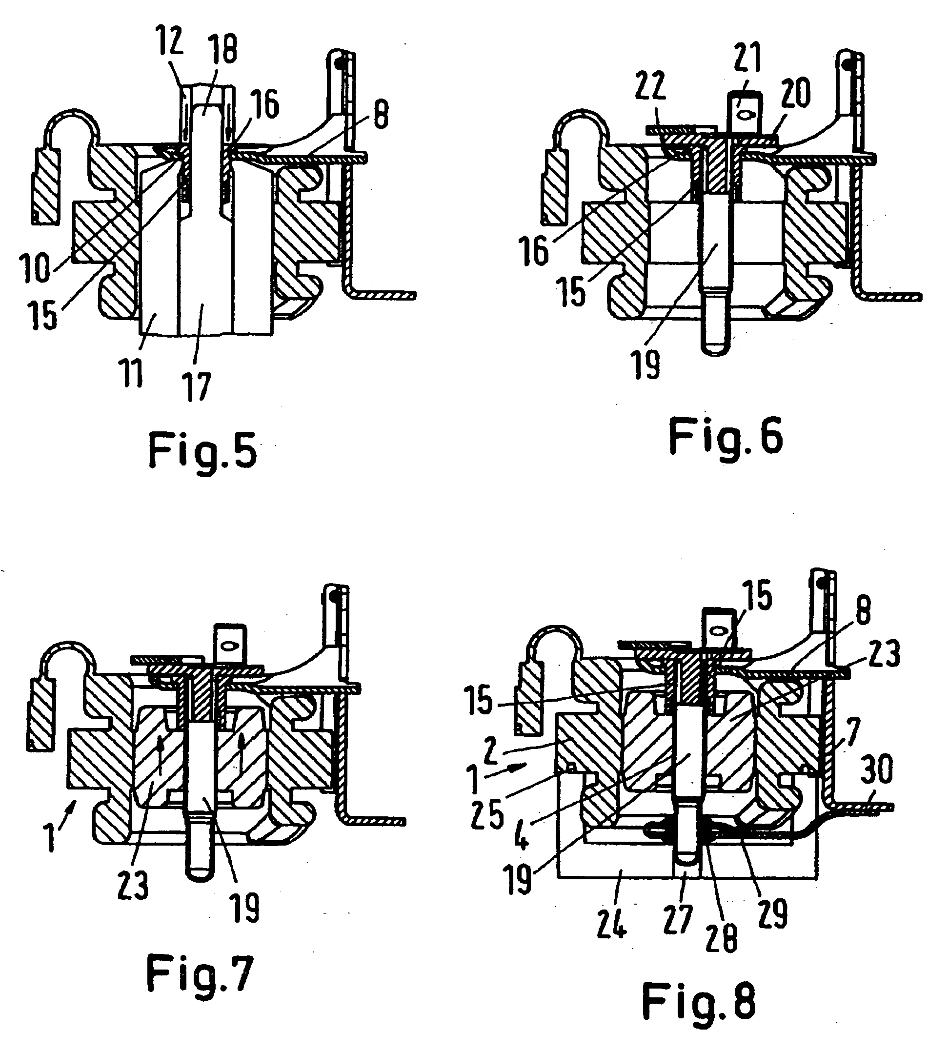
[0030]FIG. 1 shows a stator 1 of a motor, which is used for driving a compressor, particularly a refrigerant compressor. The stator 1 has a sheet pack 2 and a coil, of which coil ends 3 are shown. The sheet pack 2 surrounds a rotor opening 4. The rotor opening 4 is made in that already during the punching; the sheets forming the sheet pack 2 are provided with a central opening, so that the rotor opening 4 occurs, when the sheets of the sheet pack 2 are stacked.

[0031] A compressor block 5 is mounted and fixedly connected, for example by welding, on the outside of the sheet pack 2. The compressor block 5 can, for example, be a sheet metal part. The compressor block 5 has a basic unit 7 extending substantially parallel to the axis 6 of the stator 1, on which unit 7 a first bearing support 8 is fixed, for example by welding. After fixing on the basic unit 7, the first bearing support 8 forms a one-side suspended beam, which extends across the rotor opening 4. Both the basic unit 7 and ...


PUM

PropertyMeasurementUnit
diameteraaaaaaaaaa
radial displacementaaaaaaaaaa
energy lossesaaaaaaaaaa

Abstract

The invention concerns a method for mounting a drive shaft (19) of a compressor, particularly a hermetical refrigerant compressor, which has a motor with a stator (1) and a rotor (23), connected with the drive shaft (19) and located in a rotor opening (4) of the stator (1), a first bearing support (8) and a second bearing support (29) being connected with the stator (1), a first bearing (15) for the drive shaft (19) being mounted in the first bearing support (8) and a second bearing (28) for the drive shaft (19) being mounted in the second bearing support (29). It is endeavoured to provide a method for mounting a drive shaft, in which the use of components with relatively large manufacturing tolerances will still result in a good alignment of the drive shaft in relation to the stator. For this purpose, at least the first bearing support (8) is provided with a positioning stop for the first bearing (15) after mounting the first bearing support (8) on the stator (1).

Description

CROSS-REFERENCE TO RELATED APPLICATIONS [0001] This application is a Divisional Application of U.S. Ser. No. 11 / 135,873 entitled ‘Method for Mounting a Drive Shaft of a Compressor’, to Frank Holm Iversen, et al., filed on May 24, 2005, and claims the benefit of the filing date thereof under 35 U.S.C. §120. The present invention also claims priority from German Patent Application No. 10 2004 025 678.0, filed on May 26, 2004. The contents of both applications are incorporated by reference herein.FIELD OF THE INVENTION [0002] The invention concerns a method for mounting a drive shaft of a compressor, particularly a hermetical refrigerant compressor. BACKGROUND OF THE INVENTION [0003] Refrigerant compressors have become products manufactured in large numbers, and should therefore be manufactured in the most cost effective manner possible. As, however, refrigerant compressors are practically operating all the year round, the energy consumption of the motor, which is required for driving ...

Claims


Application Information

Patent Timeline
Patent Type & Authority Applications(United States)
IPC IPC(8): H02K5/16H02K7/08F01M1/00H02K5/167H02K7/06H02K15/02H02K15/16
CPCH02K5/1672Y10T29/53Y10T29/49009H02K15/16
Inventor IVERSEN, FRANK HOLMLASSEN, HEINZ OTTONOMMENSEN, MARTENPETERSEN, CHRISTIANSONKSEN, BEATE
Owner DANFOSS COMPRESSORS
Why Eureka
Try Eureka