Motor-drive control device and electric power steering device using the same

a technology of electric power steering and control device, which is applied in the direction of electrical steering, electronic commutators, instruments, etc., can solve the problems of motor noise increase, unfavorable phenomenon, and torque ripple of motors

Inactive Publication Date: 2006-08-10
NSK STEERING SYST +1
View PDF4 Cites 28 Cited by
  • Summary
  • Abstract
  • Description
  • Claims
  • Application Information

AI Technical Summary

Benefits of technology

[0015] The present invention relates to a motor drive control apparatus of a brushless DC motor and an electric power steering apparatus. The object of the present invention is achieved by providing a motor drive control apparatus comprising a voltage detecting section for detecting phase voltages or line voltages of a brushless DC motor having three or more phases, a current detecting section for detecting a motor current of the motor, a back-EMF detecting section for each phase for calculating a back-EMF of each phase of the motor from the phase voltages or line voltages, the motor current, the winding resistance value and winding inductance value, an angular speed calculating section which detects a back-EMF which becomes a maximum value in the back-EMF of each phase, and which calculates an angular speed ω of a rotor of the motor, and a rotor position estimating section for estimating an electrical angle θ of the rotor from the angular speed ω.
[0016] The above object of the present invention is more effectively achieved by providing the motor drive control apparatus comprising: a rotor position detecting sensor for detecting an electrical angle θ0 of the rotor of the motor in a discrete manner, and a rotor position estimating section for correcting the calculated electrical angle θ of the rotor by the detected electrical angle θ0 of the rotor; a rotor position estimating section for estimating a resistance change amount ΔR caused by temperature change of the winding resistance from an error Δθ between the calculated electrical angle θ and the detected electrical angle θ0; a rotor position estimating section for estimating a temperature change amount ΔT of the winding from the resistance change amount ΔR; a rotor position estimating section for correcting the calculated electrical angle θ of the rotor using the temperature change amount ΔT or the resistance change amount ΔR; and a rotor position estimating section in which a low pass filter is disposed in an input or output of the current detecting section.

Problems solved by technology

When such a vector control is used if the motor 56 is controlled in a state in which a rotor position θ cannot be detected precisely, the torque ripple of the motor 56 becomes large, unfavorable phenomenon is generated, for example, a driver may feel a sense of disharmony such as vibration in steering operation of a steering wheel as the electric power steering apparatus, and a motor noise is increased.
In this example, however, a rotation angle θ of the rotor in an intermediate section before a next Hall sensor signal is obtained is not calculated, and this is insufficient as a detector that can be used for detecting the rotor position unlike the encoder or resolver.
Even with a detector having excellent detection precision such as the encoder, if the rotation speed of the rotor is reduced, there is a problem that detection points obtained from the encoder are reduced and the position detecting precision of the rotor is deteriorated.
However, there exists an integration until the angular speed ω is calculated from the angular acceleration obtained based on the inertia moment and the motor current, and there also exists an integration until the electrical angle θ of the rotor is calculated from the angular speed ω. Since the integration is used two times, the calculation precision is inferior, and it is difficult to precisely determine the inertia moment of the load under which the motor is driven, there is a problem that the apparatus is put to practical use.
Therefore, if the resistance or the like caused by the temperature change is not corrected, the electrical angle θ of the rotor cannot be calculated precisely, and there is a problem that the torque ripple is increased.
To control the motor using the vector control, it is necessary to precisely detect the rotor position of the motor, but since the resolver or the encoder having excellent detection precision is expensive, this causes a bottleneck for inexpensively producing an electric power steering apparatus.
There is a problem that even if a high precision rotor position detecting sensor such as the resolver or the encoder is used, the rotor position cannot be detected precisely in a low rotation speed region of the motor.
There is also a problem that the detection precision of the rotor position is deteriorated by the temperature change of the motor.

Method used


Image

  • Motor-drive control device and electric power steering device using the same
  • Motor-drive control device and electric power steering device using the same
  • Motor-drive control device and electric power steering device using the same

Examples


Embodiment Construction

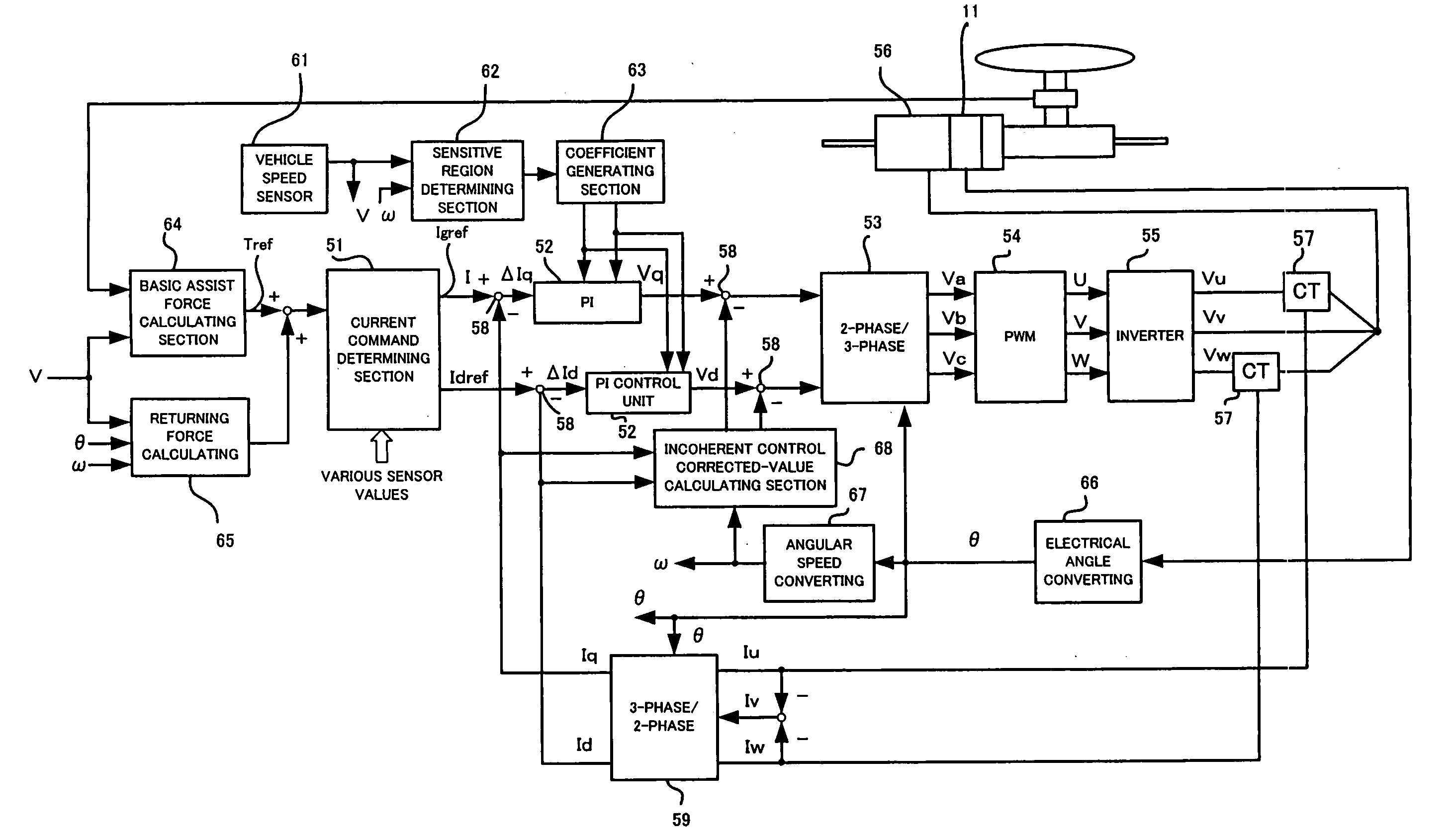
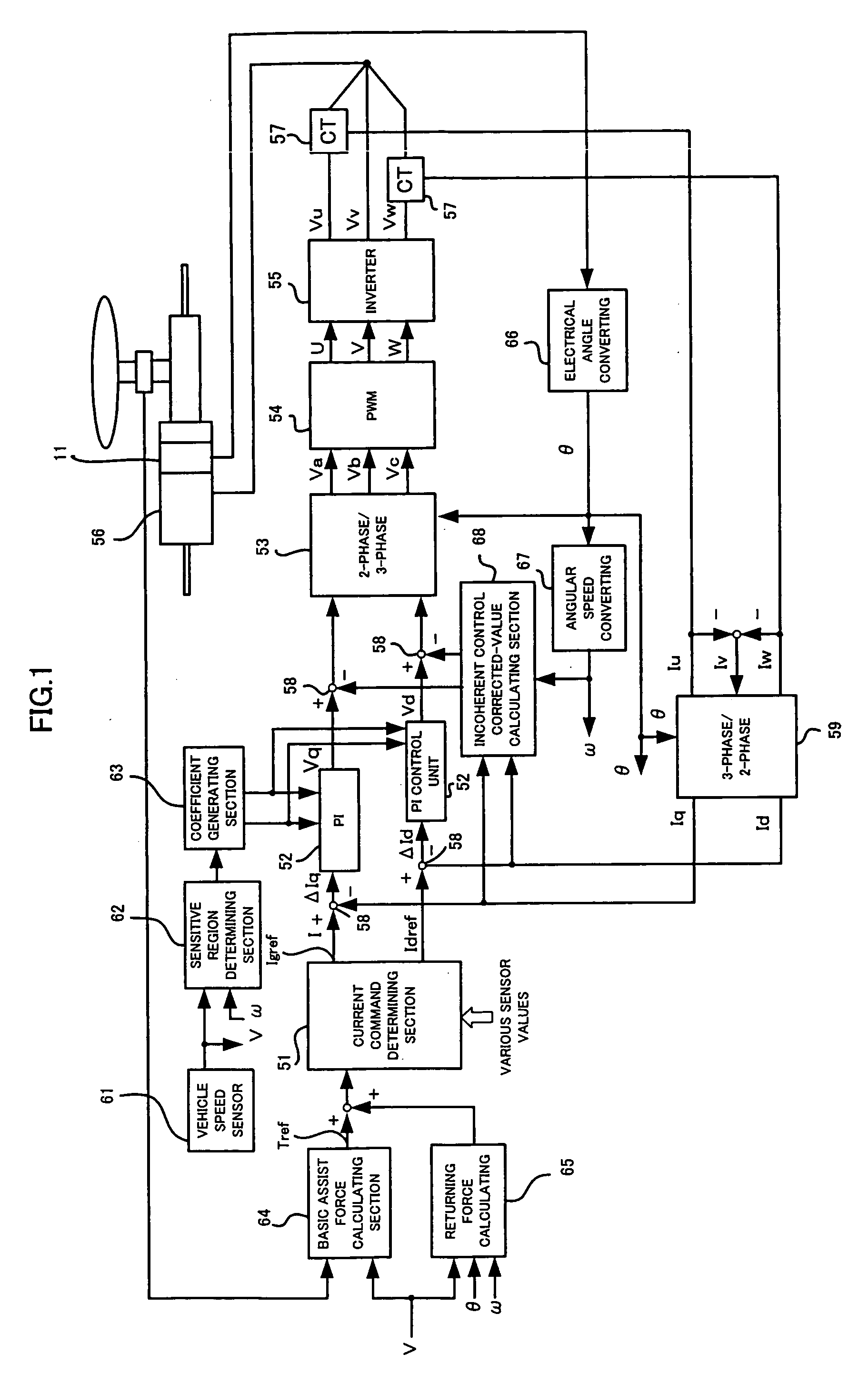
[0028] The present invention comprises four invention theories, and outlines thereof will be explained.

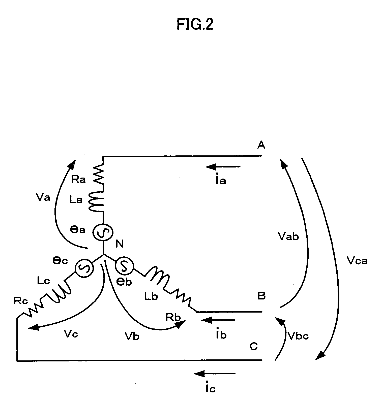
[0029] According to a first invention theory, a voltage and a current of a motor are detected, a back-EMF of each phase is calculated from the voltage value, the current value, the winding resistance R and the winding inductance L of the motor, and an angular speed ω and an electrical angle θ of a rotor are calculated from the back-EMF value.

[0030] According to a second invention theory, when there is a calculation error in the electrical angle θ calculated in the first invention theory, the error is cumulated, the error of the calculated electrical angle θ becomes excessively large, and this is not suitable for practical use. However, since several rotor phase detecting sensors such as Hall sensors capable of detecting the electrical angle of the rotor are mounted on the motor, it is possible to correct the electrical angle θ calculated in the first invention theory by the elect...


PUM


Abstract

In order to precisely control rotation of a motor, it is necessary to precisely detect a position of a rotor. Even if an inexpensive position detecting sensor having relatively low precision such as a Hall sensor is used, it is possible to provide a motor drive control apparatus capable of precisely detecting the position of the rotor by calculating an electrical angle of the rotor (rotor position) by calculating a back-EMF from a detected voltage, detected motor current, a motor winding resistance value and an inductance value, and by periodically correcting a calculation error of the calculated electrical angle. If such a motor drive control apparatus is used, it is possible to provide an inexpensive electric power steering apparatus having excellent steering feeling.

Description

TECHNICAL FIELD [0001] The present invention relates to an improvement of a drive control apparatus of a motor used for an electric power steering apparatus, and to the electric power steering apparatus using the motor drive control apparatus. BACKGROUND TECHNIQUE [0002] As a conventional drive control method of a motor used for an electric power steering apparatus, e.g., in a conventional drive control method of a brushless DC motor, there is employed a control method in which a rotating magnetic field is generated from a motor drive control apparatus through an inverter based on a rotation position of a rotor, and the rotation of the rotor is controlled. That is, according to this control method, energization of a plurality of energizing coils disposed in a state at predetermined angles in succession by a control unit in accordance with a rotor position, thereby to control the rotation of the rotor. [0003] Vector control which is frequently used as the drive control method of the ...

Claims


Application Information

Patent Timeline
Patent Type & Authority Applications(United States)
IPC IPC(8): G05F1/10H02P6/06B62D5/04H02P6/08H02P6/17H02P6/18H02P6/182H02P6/28
CPCH02P6/182H02P6/18
Inventor TA, CAOMINHJIANG, CHUNHAOKOBAYASHI, HIDEYUKI
Owner NSK STEERING SYST
Why Eureka
Try Eureka