Burn-in prevention circuit, projector, liquid crystal display apparatus, and burn-in prevention method

Inactive Publication Date: 2006-08-10
SEIKO EPSON CORP
View PDF7 Cites 12 Cited by
  • Summary
  • Abstract
  • Description
  • Claims
  • Application Information

AI Technical Summary

Benefits of technology

[0032] The offset includes at least one of the first offset and the second offset. Even when the actual value of the opposed electrode voltage is deviated from the optimum value at a certain tone level of the image signal in the liquid crystal panel, the offset including the first offset is added to the pixel electrode voltage applied to the pixel electrode of the liquid crystal panel. Even when the actual value of the opposed electrode voltage is deviated from the optimum value at a certain display position or pixel position in the image plane of the liquid crystal panel, the offset including the second offset is added to the pixel electrode voltage applied to the pixel electrode of the liquid crystal panel. In either case, the voltage actually appl

Problems solved by technology

Application of a direct current (DC) voltage to the liquid crystal for a long time period causes polarization of impurity ions inside the liquid crystal to change the physical properties of the material and decrease the resistivity.
In the actual operations, however, the alternating current actuation may not be attained to set the mean voltage applied to each pixel PE equal to 0 V, because of the reason discussed below.
This causes a burn-in of the image plane.
Such a problem also arises when the opposed electrode voltage Vcom is set to an optimum value at a pixel for whi

Method used


Image

  • Burn-in prevention circuit, projector, liquid crystal display apparatus, and burn-in prevention method
  • Burn-in prevention circuit, projector, liquid crystal display apparatus, and burn-in prevention method
  • Burn-in prevention circuit, projector, liquid crystal display apparatus, and burn-in prevention method

Examples


Embodiment Construction

[0040] One mode of carrying out the invention is discussed below as a preferred embodiment in the following sequence:

A. Structure and Operations of Signal Processing System

B. Burn-in Prevention Principle

C. Structure and Operations of Burn-in Prevention Circuit

D. Method of Detecting Optimum Value of Opposed Electrode Voltage

E. Modifications

[0041] A. Structure and Operations of Signal Processing System

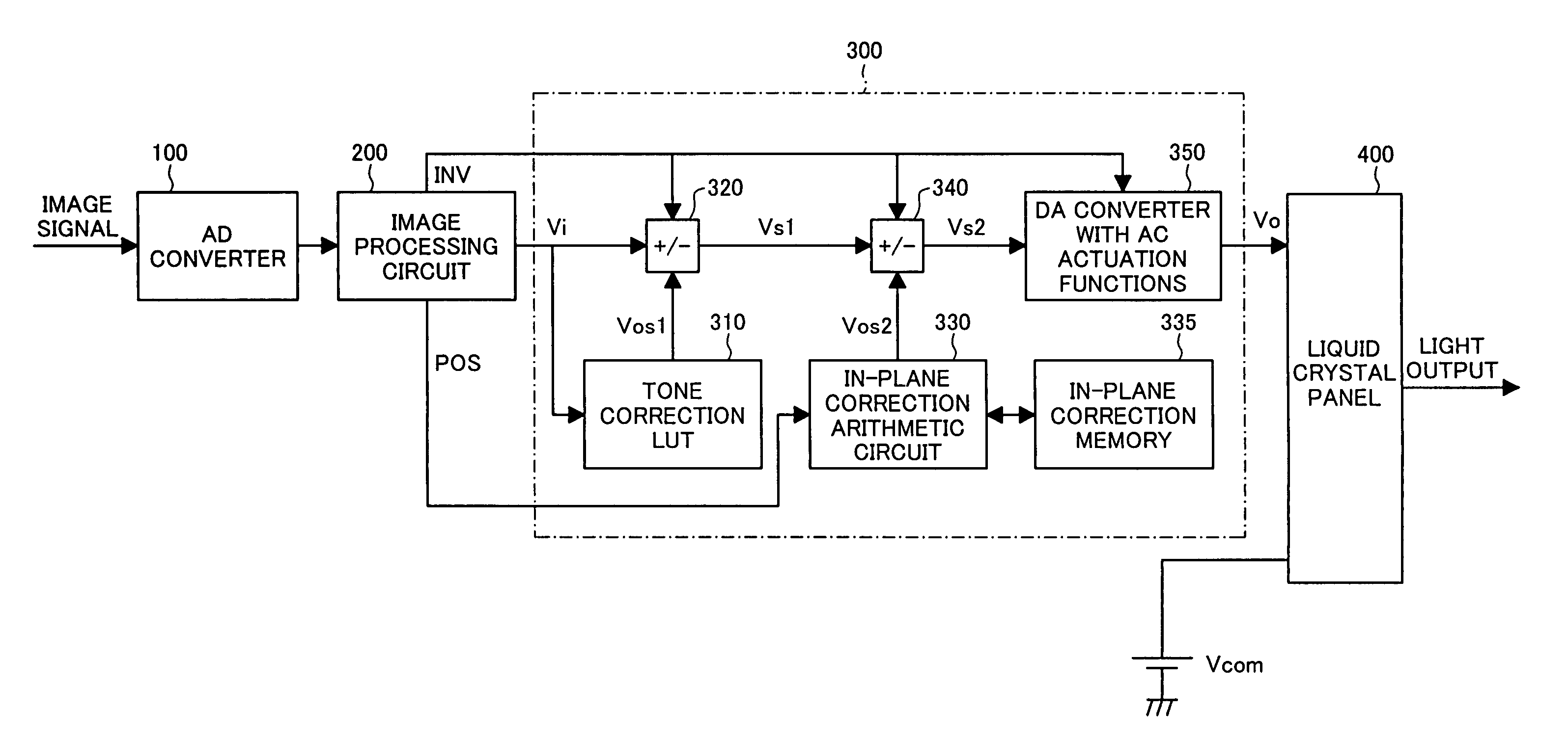
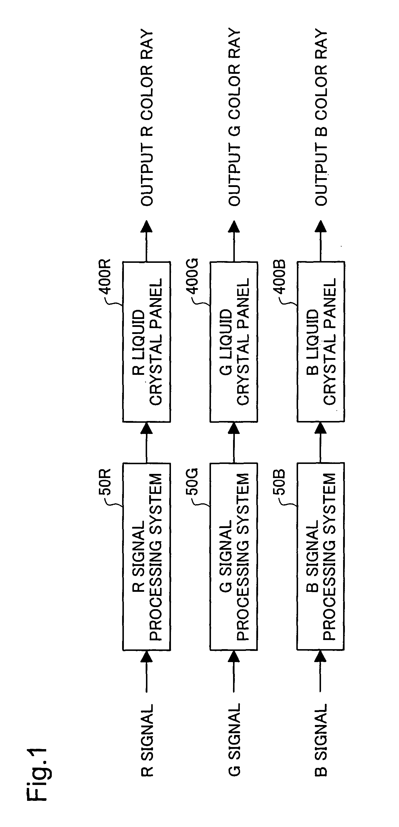
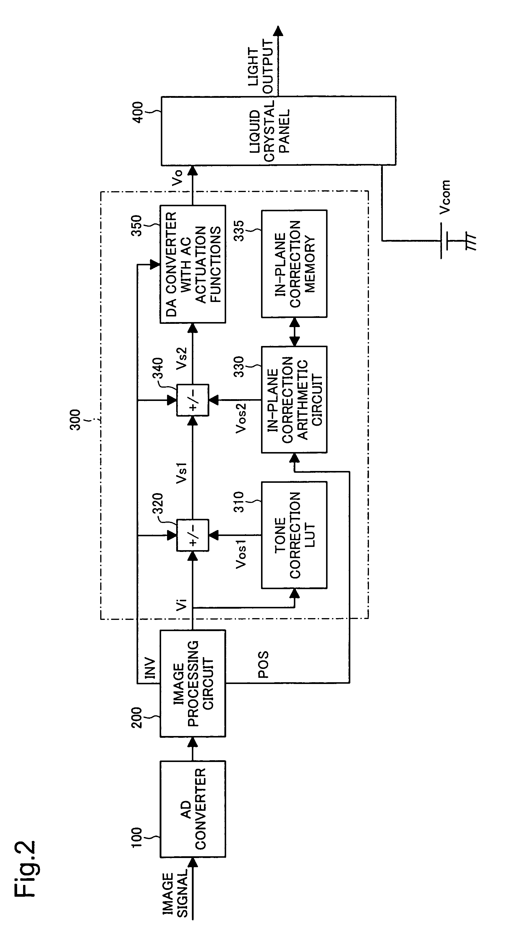
[0042]FIG. 1 is a block diagram showing the general structure of a liquid crystal projector including burn-in prevention circuits in one embodiment of the present invention. The liquid crystal projector includes three liquid crystal panels respectively corresponding to three colors R (red), G (green), and B (blue), a liquid crystal panel for the color R (hereafter referred to as R liquid crystal panel) 400R, a liquid crystal panel for the color G (hereafter referred to as G liquid crystal panel) 400G, and a liquid crystal panel for the color B (hereafter referred to as B liqu...


PUM


Abstract

A tone correction LUT 310 reads an offset Vos1 corresponding to a tone level of a digital image signal Vi and outputs the offset Vos1 to an adder-subtracter circuit 320. The adder-subtracter circuit 320 adds the offset Vos1 to the digital image signal Vi according to the polarity of a polarity specification signal INV and outputs a digital image signal Vs1. An in-plane correction arithmetic circuit 330 reads an offset Vos2 corresponding to a display position or a pixel position in response to a positioning signal POS and outputs the offset Vos2 to an adder-subtracter circuit 340. The adder-subtracter circuit 340 adds the offset Vos2 to the digital image signal Vs1 according to the polarity of the polarity specification signal INV and outputs a digital image signal Vs2. A DA converter 350 with AC actuation functions converts the digital image signal Vs2 into an analog image signal Vo, and carries out polarity inversion at each frame scanning period according to the polarity of the polarity specification signal INV, so as to output a signal allowing for AC actuation of liquid crystal. This arrangement effectively prevents a burn-in of an image plane in a liquid crystal display apparatus equipped with liquid crystal panels.

Description

BACKGROUND OF THE INVENTION [0001] 1. Field of the Invention [0002] The present invention relates to a technique of preventing a burn-in of an image plane in a liquid crystal display apparatus equipped with liquid crystal panels, for example, a liquid crystal projector. [0003] 2. Description of the Related Art [0004] Liquid crystal panels have been used widely as electro-optic devices for image formation. The liquid crystal panel applies a voltage onto liquid crystal of each pixel, in response to a pixel signal corresponding to the pixel, and regulates the transmittance of the light, with which the pixel is irradiated, so as to form an image. [0005] FIGS. 5(A) and 5(B) show an equivalent circuit to one arbitrary pixel in a liquid crystal panel and the waveform of a voltage applied to the arbitrary pixel. As shown in FIG. 5(A), one pixel PE is provided via a switching element TFT (thin film transistor) 142 at an intersection of a scanning line SL and a signal line DL crossing to each...

Claims


Application Information

Patent Timeline
IPC IPC(8): G09G3/36G09G3/20G02F1/133
CPCG09G3/3614G09G2320/046G09G3/3648G02F1/133
Inventor KOYAMA, FUMIO
Owner SEIKO EPSON CORP
Why Eureka
Try Eureka