Exposure apparatus and device manufacturing method

a technology of exposure apparatus and manufacturing method, which is applied in the direction of microlithography exposure apparatus, printers, instruments, etc., can solve the problems of poor pattern image quality, insufficient margin, and difficulty in matching the substrate surface with respect to the image plane of the projection optical system, so as to reduce the degree of cleanliness and good pattern accuracy

Inactive Publication Date: 2006-08-10
NIKON CORP +1
View PDF99 Cites 80 Cited by
  • Summary
  • Abstract
  • Description
  • Claims
  • Application Information

AI Technical Summary

Benefits of technology

[0010] The present invention was made taking such circumstances into account, and its purpose is to provide an exposure apparatus that is able to prevent pattern image deterioration and perform exposure processing with good accuracy when the pattern is exposed onto a substrate via a projection optical system and a liquid, and to provide a device manufacturing method.

Problems solved by technology

If the depth of focus δ is too narrowed, it is difficult to match the substrate surface with respect to the image plane of the projection optical system.
It is feared that the margin is insufficient during the exposure operation.
If the supply of liquid from the supply port of the liquid supply mechanism is uneven when the liquid is supplied onto the substrate to form a liquid immersion region, there is a possibility of occurrence of an inconvenience such as the formation of the liquid immersion region becoming inadequate, leading to deterioration of the pattern image exposed onto the substrate.
When the liquid cannot be adequately recovered, for example, the liquid that remains on the substrate dries, a water mark is produced there, and an inconvenience in which the remaining liquid is scattered to the peripheral mechanical components when, for example, the substrate is conveyed and rust is caused also occurs.
In addition, when liquid remains and is scattered, there is a possibility that the measuring operations relating to exposure processing will be affected, such as by fluctuations being brought about in the environment (temperature, etc.) in which the substrate is placed, causing changes in the refractive index on the optical path of the detection light of the optical interferometer used in stage position measurement, thereby causing exposure precision to degraded.

Method used


Image

  • Exposure apparatus and device manufacturing method
  • Exposure apparatus and device manufacturing method
  • Exposure apparatus and device manufacturing method

Examples


Embodiment Construction

[0043] The exposure apparatus of the present invention will be explained below while referring to the drawings. However, the present invention is not limited to the respective embodiments below, and, for example, the constituent elements of these embodiments may be appropriately combined.

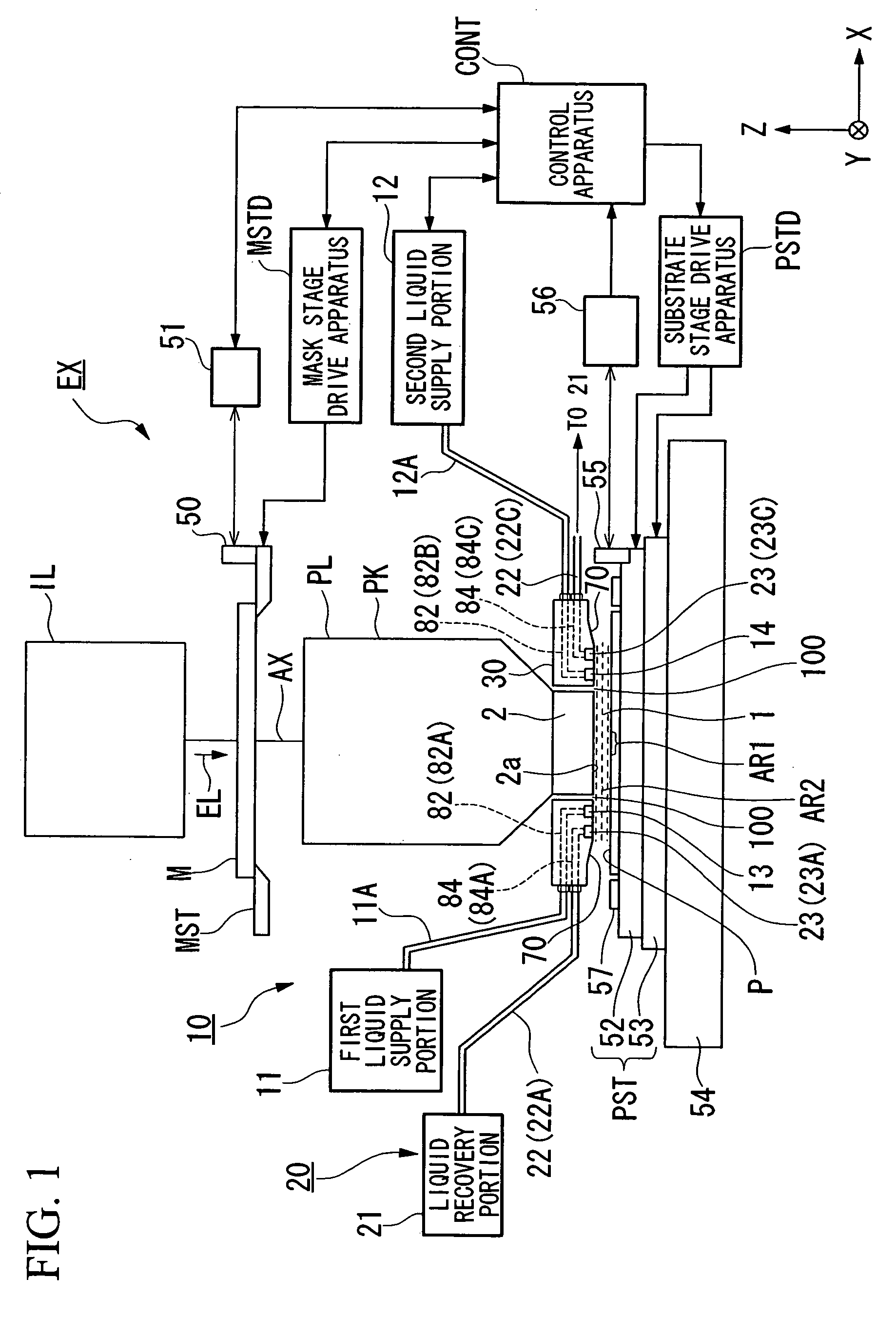
[0044]FIG. 1 is a schematic block diagram that shows one embodiment of the exposure apparatus of the present invention.

[0045] In FIG. 1, the exposure apparatus EX is provided with a mask stage MST that supports a mask M, a substrate stage PST that supports a substrate P, an illumination optical system IL that uses exposure light EL to illuminate the mask M that is supported by the mask stage MST, a projection optical system PL that projection exposes the pattern image of the mask M illuminated by the exposure light EL onto the substrate P supported on the substrate stage PST, and a control apparatus CONT that comprehensively controls operation of the entire exposure apparatus EX.

[0046] The exposu...


PUM

PropertyMeasurementUnit
refractive indexaaaaaaaaaa
wavelengthaaaaaaaaaa

Abstract

An exposure apparatus exposes a substrate by forming a liquid immersion region on the substrate, and projecting a pattern image onto the substrate via a projection optical system and a liquid that forms the liquid immersion region. The exposure apparatus includes: a liquid supply mechanism that has a supply port arranged to oppose a surface of the substrate; and a buffer space formed in a channel of the liquid supply mechanism; wherein the liquid is supplied to the supply port after reserving a prescribed amount or more of liquid in the buffer space.

Description

CROSS-REFERENCE TO RELATED APPLICATION [0001] This is a Continuation Application of International Application No. PCT / JP2004 / 010057, filed Jul. 8, 2004, which claims priority to Japanese Patent Application No. 2003-272617 (filed on Jul. 9, 2003). The contents of the aforementioned application are incorporated herein by reference. BACKGROUND OF THE INVENTION [0002] 1. Field of the Invention [0003] The present invention relates to an exposure apparatus that exposes a pattern on a substrate via a projection optical system and a liquid and to device manufacturing method. [0004] 2. Description of Related Art [0005] The semiconductor device or the liquid crystal display device is manufactured by the technique known as photolithography, in which a pattern formed on a mask is transferred onto a photosensitive substrate. The exposure apparatus used in this photolithography process has a mask stage that supports a mask and a substrate stage that supports a substrate, and it transfers a mask p...

Claims


Application Information

Patent Timeline
Patent Type & Authority Applications(United States)
IPC IPC(8): G03B27/42G03F7/20
CPCG03F7/70341G03F7/70883
Inventor NAGASAKA, HIROYUKIOKUYAMA, TAKESHI
Owner NIKON CORP
Why Eureka
Try Eureka