
Optical system for a wash light

a technology of optical system and wash light, which is applied in the field of optical system, can solve the problems of high cost of materials used to filter the color of the light beam in the fixture, and the inability to consider the diffuse beam by users as a suitable replacement for the beam from the parabolic optical system

Active Publication Date: 2006-08-10
WHITEROCK DESIGN
View PDF22 Cites 11 Cited by
  • Summary
  • Abstract
  • Description
  • Claims
  • Application Information

AI Technical Summary

Benefits of technology

[0015] The present invention provides a wash light optical system for use with an ellipsoidal reflector. The optical system may be enclosed in a housing that may be detachably mounted to a lamp housing of an existing ellipsoidal reflector spotlight. The optical system may be employed in an ellipsoidal wash light fixture using the same ellipsoidal reflector as an ellipsoidal reflector spot lighting fixture. The optical system may be designed to have a short overall length and to use a reduced amount of color filter material.
[0016] More specifically, aspects of the invention may be found in an optical system for use with a light beam generator. The optical system includes a converging optical element that reduces the size of a light beam from the light beam generator. The optical system also includes a color filtering mechanism that is capable of filtering the light beam to a selected one of two or more colors. A spreading optical device in the optical system increases the size of the light beam, which then passes through a beam shaping optical device. The optical system may also include a dimming mechanism that is capable of reducing the intensity of the light beam to a selected one of two or more intensities. The optical system may be enclosed in a housing that includes a coupling mechanism capable of detachably mounting the housing to the light beam generator.
[0017] Other aspects of the invention may be found in a light fixture that includes a light beam generator. The light fixture also includes a converging optical element that reduces the size of a light beam from the light beam generator. The light fixture further includes a color filtering mechanism that is capable of filtering the light beam to a selected one of two or more colors. A spreading optical device in the light fixture increases the size of the light beam, which then passes through a beam shaping optical device. The light fixture may also include a dimming mechanism that is capable of reducing the intensity of the light beam to a selected one of two or more intensities.
[0019] Aspects of the invention may also be found in a method of producing a light fixture capable of generating a light beam having a desired color and shape. The method includes providing a housing that includes a coupling mechanism and encloses an optical system. The method also includes detachably mounting the housing to a light beam generator using the coupling mechanism. The optical system includes a converging optical element that reduces the size of a light beam from the light beam generator. The optical system also includes a color filtering mechanism that is capable of filtering the light beam to a selected one of two or more colors. A spreading optical device in the optical system increases the size of the light beam, which then passes through a beam shaping optical device.

Problems solved by technology

However, such diffused beams are often not considered by users as a suitable replacement for a beam from a parabolic optical system or an ellipsoidal optical system with a non-imaging lens.
Second, while a large beam size from the fixture is generally desirable, the materials used to filter the color of the light beam in the fixture may be expensive, leading to a desire to minimize the amount of filter material used in each fixture.

Method used


Image

  • Optical system for a wash light
  • Optical system for a wash light
  • Optical system for a wash light

Examples


Embodiment Construction

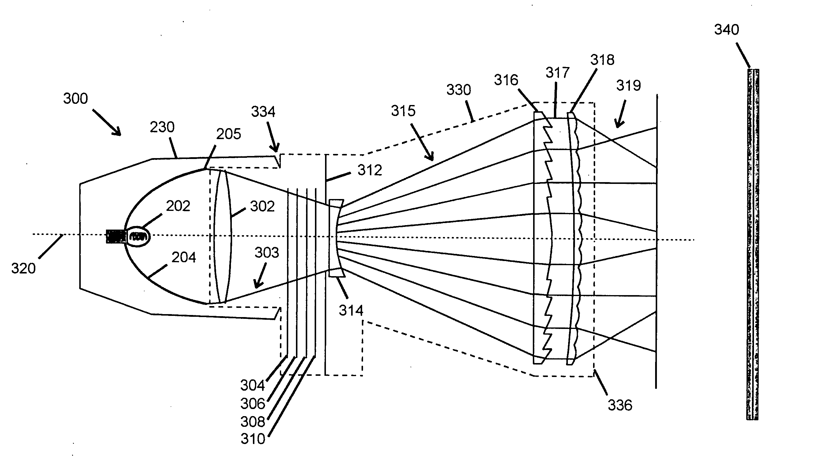
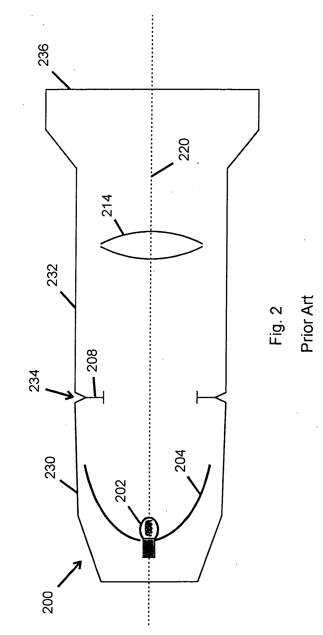
[0026]FIG. 3 presents a schematic cross-section view of an optical system according to the present invention that mounts on the reflector housing 230 of the ERS 200 shown in FIG. 2 to form an ellipsoidal reflector wash light fixture 300. An optical system housing 330 is detachably mounted to the reflector housing 230 by a coupling mechanism 334.

[0027] An optical system embodying the present invention may include a converging optical element 302 that accepts a light beam emerging from the rim 205 of the ellipsoidal reflector 204. The converging optical element 302 produces a converging light beam 303, which converges toward a field stop plate 312. The field stop plate 312 blocks any light rays outside the desired contours of the light beam 303.

[0028] In the embodiment of the present invention shown in FIG. 3, the converging optical element 302 is a lens having a positive focal length, a so-called ‘positive’ lens. It will be understood that alternative optical elements may be employ...


PUM


Abstract

A wash light optical system for use with a light beam generator includes a converging optical element that reduces the size of a light beam from the light beam generator, a color filtration mechanism that is capable of filtering the reduced light beam to a selected one of two or more colors, a spreading optical element that increases the size of the filtered light beam, and a beam shaping optical element. The optical system may also include a dimming mechanism that is capable of reducing the intensity of the light beam to a selected one of two or more intensities. The optical system may be enclosed in a housing that includes a coupling mechanism capable of detachably mounting the housing to the light beam generator.

Description

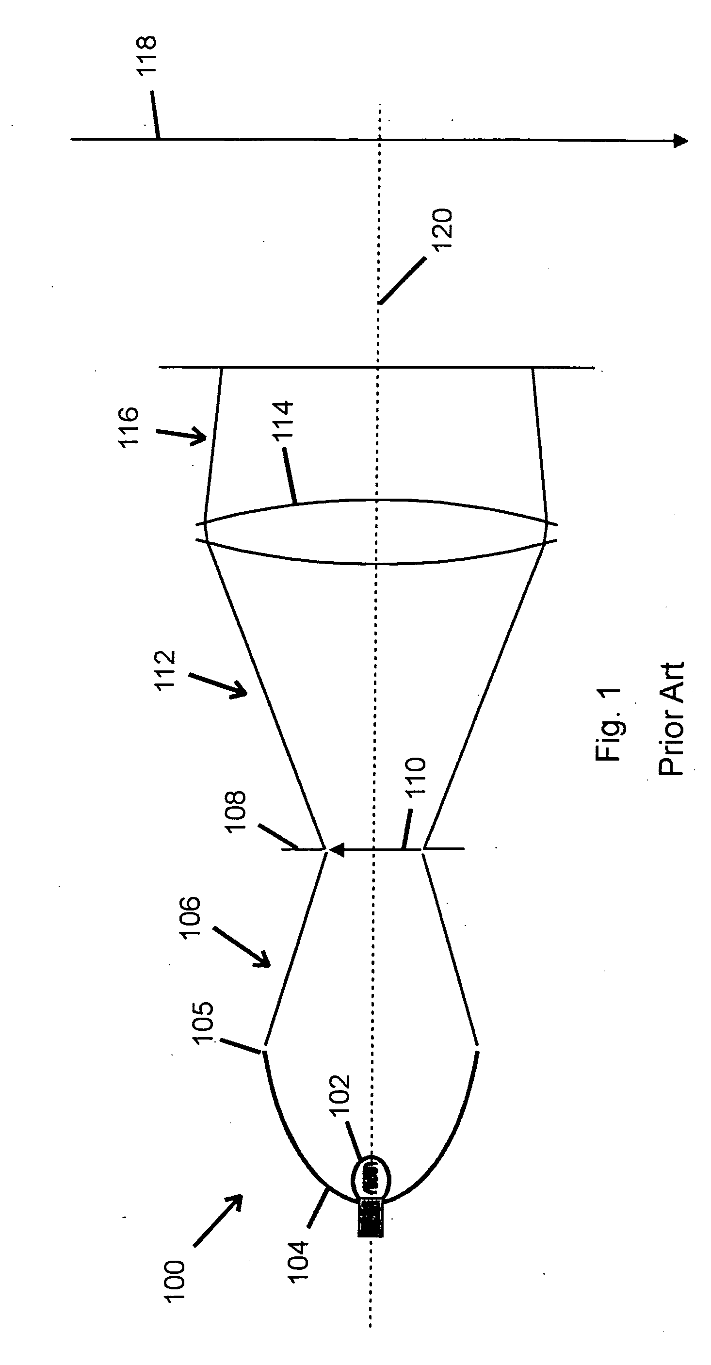
CROSS-REFERENCE TO RELATED APPLICATIONS [0001] This application claims priority under 35 U.S.C. § 119(e) to U.S. Provisional Application No. 60 / 649,983, filed on Feb. 4, 2005, which is hereby incorporated by reference.TECHNICAL FIELD OF THE INVENTION [0002] The present invention relates to optical systems and, more particularly, to an optical system for a wash light. BACKGROUND OF THE INVENTION [0003] The Ellipsoidal Reflector Spotlight (ERS) and the Parabolic Wash light (PAR) are two of the most popular lighting fixtures used in theatre, television, and architectural lighting. An ERS employs a reflector generated from an ellipsoidal or near-ellipsoidal curve rotated about the longitudinal axis of the optical system to define a reflecting surface, typically referred to as an ellipsoidal reflector. An ERS also produces a beam with a sharp edge, which, if projected on a flat surface, results in a ‘spot’ of light. [0004] In a PAR optical system, a parabolic or near-parabolic curve is u...

Claims


Application Information

Patent Timeline
Patent Type & Authority Applications(United States)
IPC IPC(8): F21S8/00F21V9/00F21V9/40
CPCF21S10/02F21V5/04F21V5/045F21V9/10F21W2131/406F21V9/40
Inventor HOUGH, THOMAS A.
Owner WHITEROCK DESIGN
Learn More