Apparatus for resin-impregnation of fibers for filament winding

a technology of filament winding and filament, which is applied in the direction of liquid/gas/vapor textile treatment, textiles, coatings, etc., can solve the problems of increasing the time required for clean-up, break-down and set-up of the system, and significant resin waste during processing and cleaning. achieve the effect of increasing the rate at which reinforcement materials can be impregnated, reducing and increasing the number of filament windings

Inactive Publication Date: 2006-08-10
TSE INDS
View PDF8 Cites 18 Cited by
  • Summary
  • Abstract
  • Description
  • Claims
  • Application Information

AI Technical Summary

Benefits of technology

[0012] The present invention provides a novel apparatus for use in the process of filament winding parts or articles. It provides a resin impregnation system whereby reinforcement material is passed through a “drip-less” two roll impregnator, wherein the reinforcing fibers are simultaneously saturated, impregnated, degassed, and nipped, preferably employing a thermosetting resin (i.e. polyester, epoxy, vinyl ester, polyurea, isocyanurate, polyurethane, etc.). In one embodiment, the invention involves passing reinforcement material, prior to being wound onto a mandrel or preformed shape, between two impregnation rollers whereby the reinforcement material is impregnated with resin material. The impregnation rollers are capable of increasing the rate at which reinforcement material can be impregnated while continually yielding complete impregnation of the reinforcement fibers. Further, the impregnation rollers allow for the processing of more advanced resin systems (i.e. systems with higher viscosities and faster gel times) and heavy reinforcement materials that were previously unusable in filament winding processes. The finished parts or articles filament wound using this novel impregnation apparatus exhibit reduced voids due to entrapped air. Moreover, the nipping effect of the impregnation rollers coupled with the small bath-like resin area within the rollers and the “drip-less” resin reclaiming dams, provide for improved resin utilization and minimal waste.

Problems solved by technology

Setup of the system can be difficult and time consuming, especially as the size of the bath and the number of bars through which the fibers are weaved increases.
Generally speaking, the bath is a messy operation and requires an extreme excess of resin to insure saturation of the fibers, resulting in significant resin waste during processing and clean-up.
The process also involves many resin-wetted parts, which increases the time required for clean-up, break-down and set-up of the system.
These systems are also limited to employing resins with long gel times so as to maintain a sufficiently low viscosity within the bath to consistently wet-out the fibers, and especially, to avoid gelling the large volume of resin within the bath.
Running time is often limited due to gelation of resin in stagnant areas of the resin bath, requiring shut down, removal of resin, clean up, and restart.
This tension increases the wearing of the glass and negatively affects the strength of the finished part.
This air is then entrapped within the filament wound part causing voids within the laminate, and thus weakening the part.
During squeezing the brass and rubber edges of the bushings exert force and tension on the fibers in order to squeeze out the excess resin and as a result the fiber is put under increasing stress that causes the fiber to break and “fray” which weakens the part, creates the need to clean the applicator and tooling more frequently, and worsens the aesthetics of the finished composite part or article.
Setup of the system can be difficult and time consuming especially when a roller and doctor blade are used for resin impregnation.
In these systems, controlling the thickness of the adhering resin layer is very difficult.
Also, the speed and tension with which the fiber is drawn changes the impregnation roller speed which in turn affects the hydraulic pressure of the resin between the doctor blade and the resin impregnation roller.
Finally, the doctor blade is set while the system is stopped and cannot generally be adjusted while the fiber is being drawn over the impregnation roller.
Therefore, in systems like this, controlling the doctor blade is very difficult, but is critical to ensuring the proper amount of resin is incorporated into the fiber.
A further and important drawback is that a large areal surface of resin is exposed to the air on the rollers, which will cause advancement of certain of the resins, particularly those which are moisture sensitive.
This may lead to non-uniform impregnation and poor incorporation into the final manufactured part.
Replacement of the resin is wasteful and further requires disposal of unused hazardous materials, which increases manufacturing costs significantly.
However, such injection or manifold applicators tend to apply increasing tension and cause fiber wear at high speeds due to the friction caused by squeezing the fibers through a die or manifold in which the contact edges are static (i.e. non-rotating).
As previously stated, when the fiber is put under increasing stress the fiber will break and “fray” which weakens the part, creates the need to clean the applicator and tooling more frequently, and worsens the aesthetics of the finished composite part or article.
Thus, to date, balancing consistent wetting and full impregnation while delivering increased line speeds with minimal air entrapment, tension, and detriment to fibers caused by the fraying of these fibers has proven difficult to achieve.
Furthermore, balancing the resin to glass ratio so as to promote maximum impregnation, while leaving minimal excess resin to be lost during the processing of the reinforcement fibers has also proven difficult using these traditional impregnation means (i.e. baths, applicator rollers, etc.).

Method used


Image

  • Apparatus for resin-impregnation of fibers for filament winding
  • Apparatus for resin-impregnation of fibers for filament winding
  • Apparatus for resin-impregnation of fibers for filament winding

Examples


Embodiment Construction

)

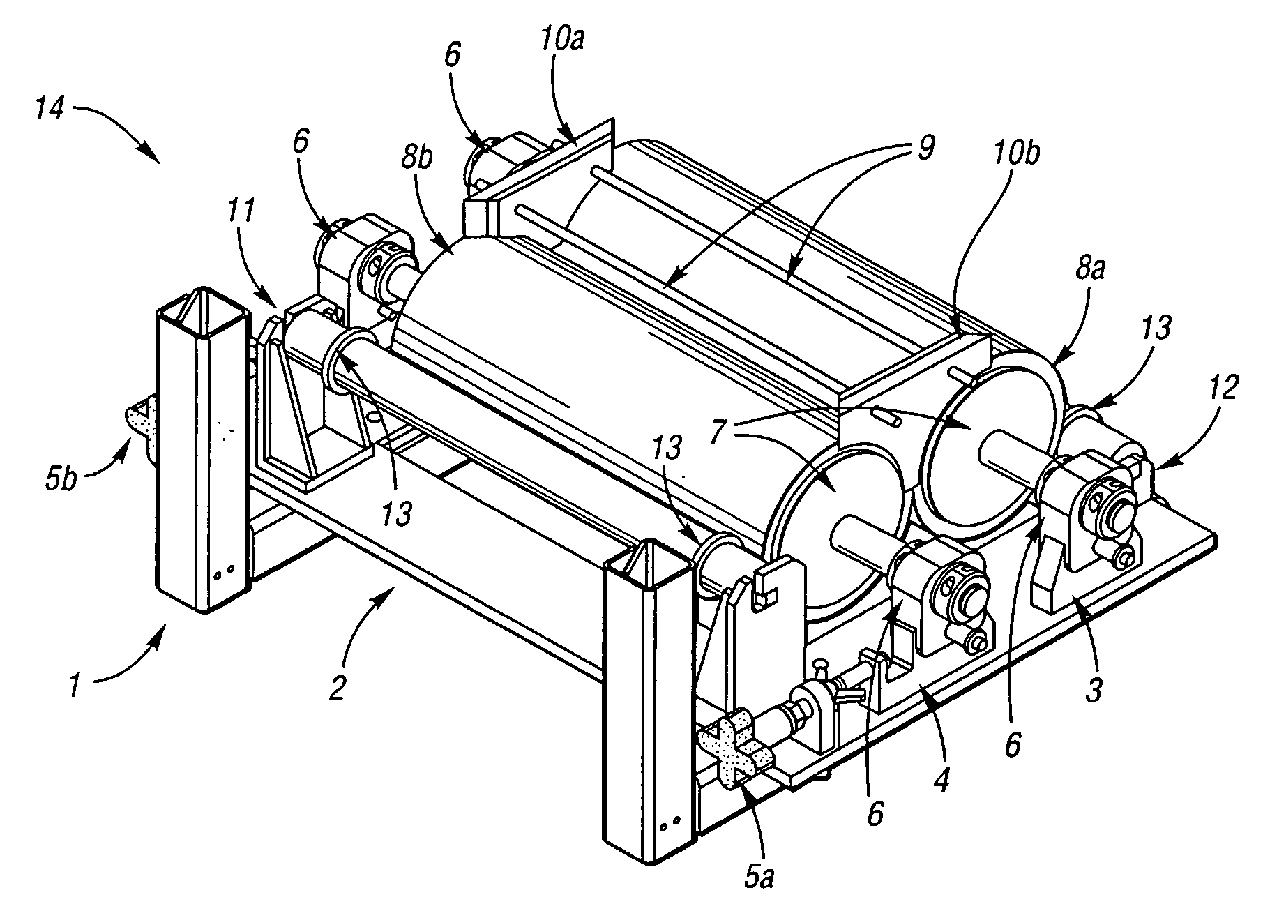
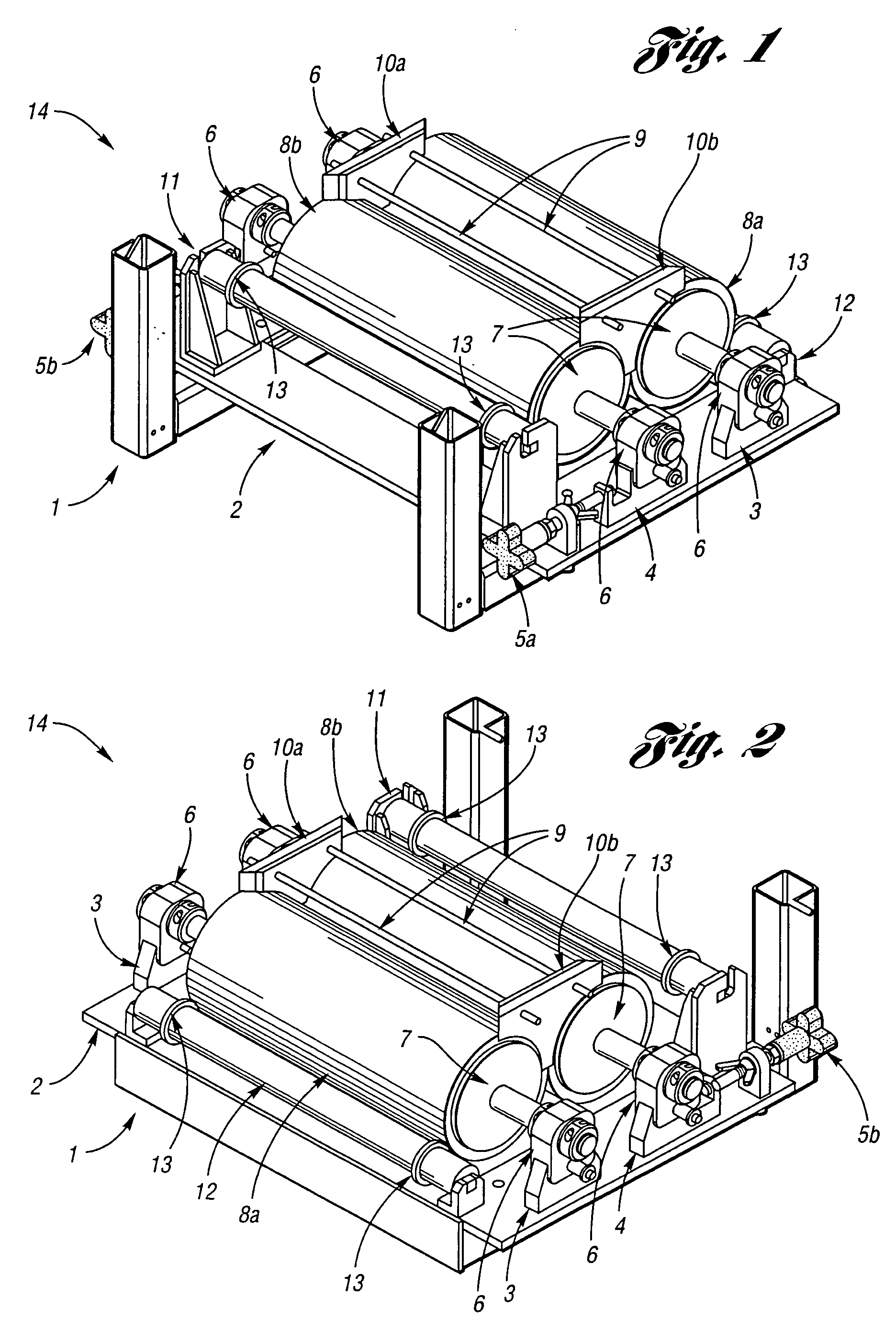
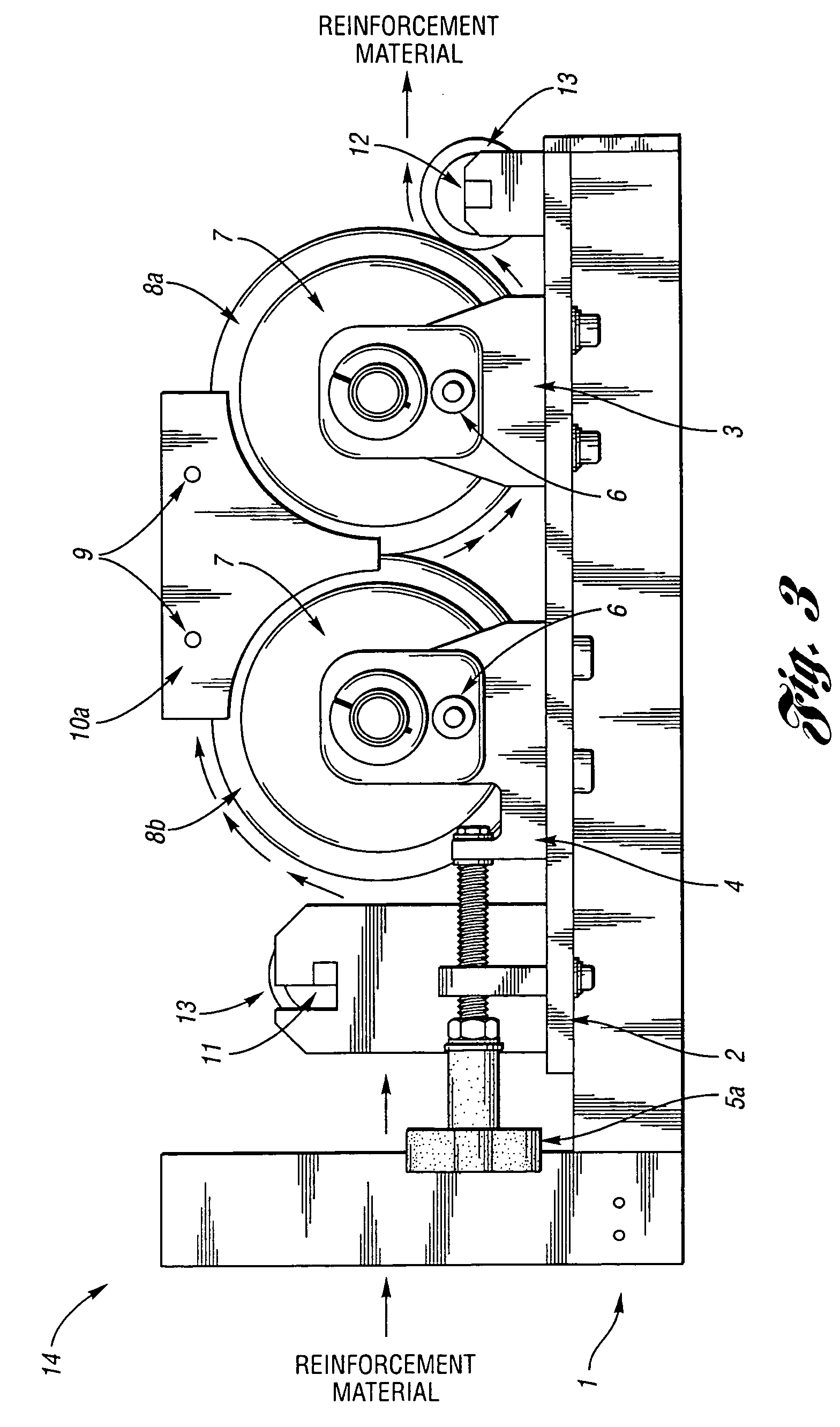
[0018] While this invention may be embodied in many different forms, there are described in detail herein specific preferred embodiments of the invention. This description is an exemplification of the principles of the invention and is not intended to limit the invention to the particular embodiments illustrated. Furthermore, while the apparatus is described for use in preparing fiber reinforcement for use in filament winding processes, the apparatus may also be used to impregnate fiber reinforcement with resin for use in other processes as well, for example the preparation of prepreg materials.

[0019] Thus, one aspect of the invention pertains to a process for the impregnation of fiber reinforcement for use in filament winding, this process including the steps of: supplying at least one continuous fiber reinforcing material; passing the fiber reinforcing material around a tensioning device and over a first cylindrical impregnation roller; passing the fiber reinforcing material thr...


PUM

PropertyMeasurementUnit
thicknessaaaaaaaaaa
thicknessaaaaaaaaaa
strengthaaaaaaaaaa

Abstract

A two roll impregnator for impregnating fiber reinforcement for use in filament winding operatives contains two abutting rolls, at least one and preferably both having an elastomeric surface. Resin is constrained within a bath whose lower surfaces are defined by the abutting rollers and side dams. Fiber reinforcement is drawn over a first roller through the resin bath and between the closed nip of the abutting rollers, where full impregnation is fostered, excess resin removed, and the impregnated fiber degassed. Substantially dripless operation can be maintained.

Description

CROSS-REFERENCE TO RELATED APPLICATIONS [0001] This application claims the benefit of U.S. provisional application Ser. No. 60 / 650,289, filed Feb. 4, 2005.BACKGROUND OF THE INVENTION [0002] 1. Field of the Invention [0003] The present invention relates an apparatus for use in impregnating fiber reinforcement with a resin for use in filament winding operations, to a process for the preparation of resin impregnated fiber reinforcement using the apparatus, and to filament winding employing resin impregnated reinforcing fibers produced thereby. [0004] 2. Description of the Related Art [0005] Filament winding processes for preparing fiber-reinforced articles are now well established. Typically in such processes, resin impregnated strands, yarn, fabric, or tape of high-strength reinforcement fibers are used when making filament wound articles. Traditionally, these fibers are impregnated using thermosetting resins such as unsaturated polyester, epoxy, vinyl ester, polyurea, isocyanurate, a...

Claims


Application Information

Patent Timeline
Patent Type & Authority Applications(United States)
IPC IPC(8): B05D1/18B05C3/12
CPCB29B15/122B29C53/8066D06B1/145
Inventor RADAY, ROBERT M.
Owner TSE INDS
Why Eureka
Try Eureka