Circuit for controlling arc energy from an electrosurgical generator

a generator and circuit technology, applied in the field of electrosurgical surgery, can solve the problems of difficult prediction and control of the depth of ablation, undesirable collateral damage to critical tissue and/or organs, and the inability of electrosurgical generators to vary the amount of energy, etc., to minimize the amount of tissue vaporization, limit thermal spread, and minimize current

Inactive Publication Date: 2006-08-10
COVIDIEN AG
View PDF99 Cites 68 Cited by
  • Summary
  • Abstract
  • Description
  • Claims
  • Application Information

AI Technical Summary

Benefits of technology

[0009] A circuit is disclosed which minimizes the amount of tissue vaporized during a first half (positive half cycle) of an electrosurgical current cycle and minimizes the amount of current applied to tissue during a second half (negative half cycle) of the electrosurgical current cycle to limit thermal spread. The circuit is provided within an electrosurgical generator to provide an electrosurgical generator which is capable of controlling the amount of energy delivered to a patient during electrosurgery on a per arc basis.
[0012] In alternate embodiments, the resistors of the diode-resistor block are replaced with potentiometers for allowing a user of the electrosurgical generator to “dial ” in preferred levels of tissue vaporization and thermal spread. With these embodiments, the surgeon is given an almost unlimited ability to vary the ratio between the amount of tissue vaporized and thermal spread.

Problems solved by technology

Electrosurgical generators do not have the ability to vary the amount of energy contained within an arc to control the amount of tissue vaporized and the amount of current applied to tissue to limit collateral damage to surrounding tissue, e.g., thermal spread.
As can be appreciated, by not controlling the thermal spread the depth of ablation is difficult to predict and control.
Electrosurgery is thus disadvantageous in applications in which only a fine layer of tissue is to be ablated, or in areas of the body such as the heart or near the spinal cord where resistive heating can result in undesirable collateral damage to critical tissue and / or organs.
The spark gap limits the arc energy, but is prone to introducing high frequency oscillations that can have an undesirable effect on the tissue, as well as increase the high frequency leakage currents.

Method used


Image

  • Circuit for controlling arc energy from an electrosurgical generator
  • Circuit for controlling arc energy from an electrosurgical generator
  • Circuit for controlling arc energy from an electrosurgical generator

Examples


Embodiment Construction

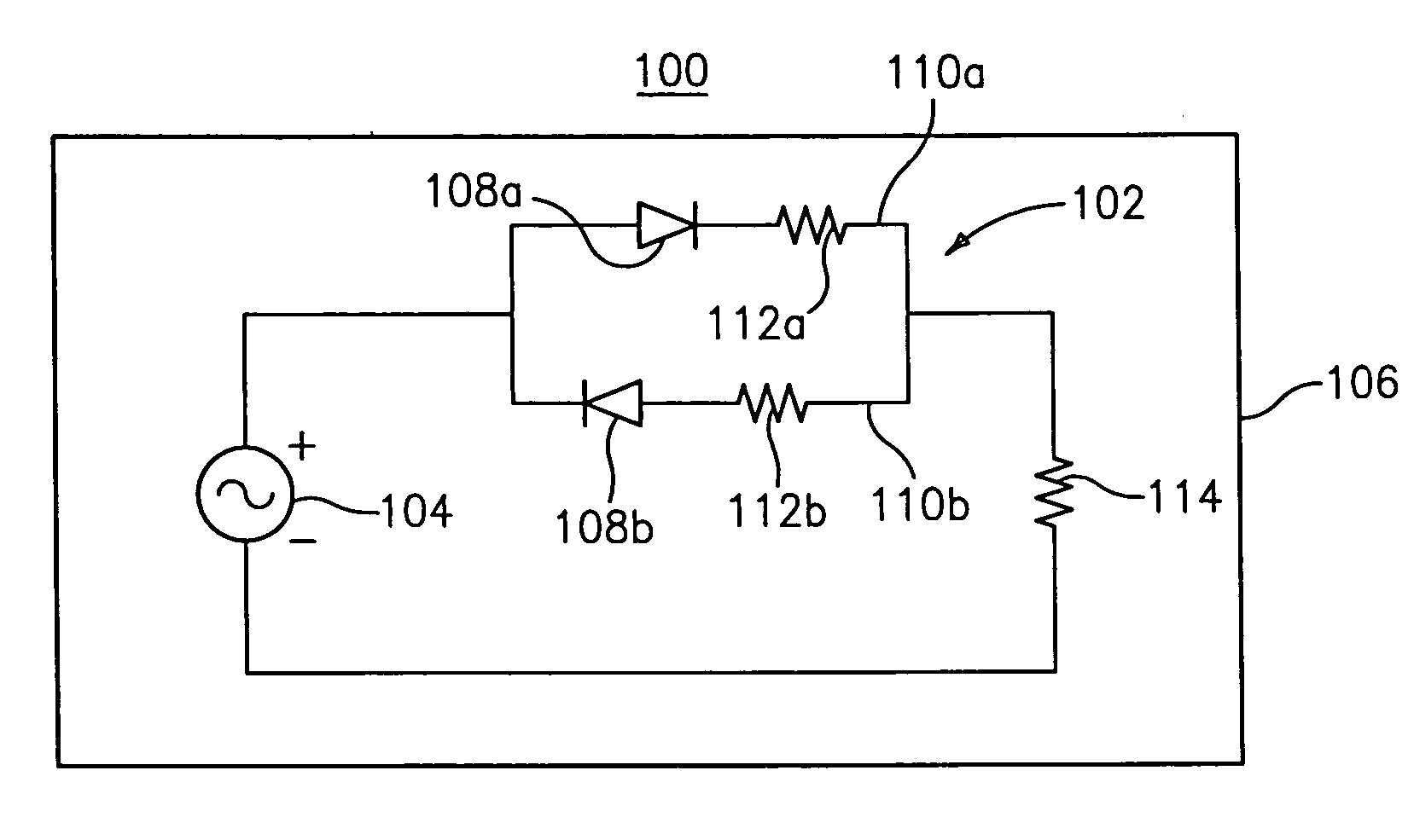
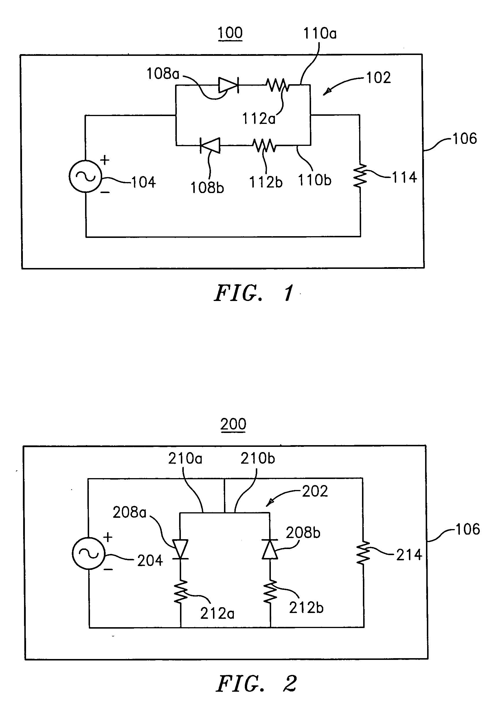
[0021] Reference is made to the drawings where like reference numerals refer to similar elements. Referring to FIG. 1, there is shown a schematic diagram of a circuit according to one embodiment of the present disclosure generally identified by reference numeral 100. Circuit 100 includes a diode-resistor block 102 in series with an output current 104 of an electrosurgical generator 106. The diode-resistor block 102 includes a pair of diodes 108a, 108b biased opposite from each other, thus splitting the output current 104 into two paths 110a, 110b. Preferably, the diodes 108a and 108b are high voltage, fast recovering diodes.

[0022] The diode-resistor block 102 further includes resistors 112a, 112b in each of these two paths 110a, 110b. These resistors 112a, 112b, depending on their resistive value (including having no resistive value, i.e., short), limit the current for each half cycle of the output current 104. Preferably, the resistance value for resistors 112a and 112b is in the ...


PUM


Abstract

A circuit is disclosed which minimizes the amount of tissue vaporized during a first half (positive half cycle) of an electrosurgical current cycle and minimizes the amount of current applied to tissue during a second half (negative half cycle) of the electrosurgical current cycle to control thermal spread. The circuit is preferably provided within an electrosurgical generator which is capable of controlling the amount of energy delivered to a patient during electrosurgery on a per arc basis.

Description

CROSS REFERENCE TO RELATED APPLICATIONS: [0001] This application is a continuation of U.S. application Ser. No. 10 / 728,212 filed on Dec. 4, 2003 by David S. Keppel entitled “CIRCUIT FOR CONTROLLING ARC ENERGY FROM AN ELECTROSURGICAL GENERATOR”, the entire contents of which are hereby incorporated by reference herein.BACKGROUND [0002] 1. Technical Field [0003] The present disclosure is directed to electrosurgery and, in particular, to circuitry for controlling arc energy from an electrosurgical generator for ablating, cauterizing, coagulating, cutting and / or sealing body tissue during electrosurgery. [0004] 2. Description of the Related Art [0005] Electrosurgical generators do not have the ability to vary the amount of energy contained within an arc to control the amount of tissue vaporized and the amount of current applied to tissue to limit collateral damage to surrounding tissue, e.g., thermal spread. The ultimate amount of arc energy from the electrosurgical generator to the tiss...

Claims


Application Information

Patent Timeline
Patent Type & Authority Applications(United States)
IPC IPC(8): A61B18/12A61B18/14
CPCA61B18/1206A61B2018/00875A61B2018/1213
Inventor KEPPEL, DAVID S.
Owner COVIDIEN AG
Why Eureka
Try Eureka