Hydraulic equipment with built-in free piston

a technology of hydraulic equipment and free piston, which is applied in the direction of vibration dampers, shock absorbers, accumulations, etc., can solve the problems of unstable damping characteristics, unfavorable effect on the response and reliability of hydraulic equipment, etc., and achieves good responsiveness, high elasticity, and compensating the effect of variable capacity of liquid chambers

Inactive Publication Date: 2006-08-17
KYB CORP
View PDF2 Cites 17 Cited by
  • Summary
  • Abstract
  • Description
  • Claims
  • Application Information

AI Technical Summary

Benefits of technology

[0008] According to this prior art, even if frictional resistance between the free piston and the inner circumference of the cylinder prevents the free piston from sliding, since the bladder expands or shrinks without delay, the variation in the capacity of the liquid chamber can be compensated with good responsiveness.
[0009] Rubber having high elasticity is used for th

Problems solved by technology

This operation characteristic of a free piston may bring about an unfavorable effect on the response and reliability of hydraulic equipment that h

Method used


Image

  • Hydraulic equipment with built-in free piston
  • Hydraulic equipment with built-in free piston
  • Hydraulic equipment with built-in free piston

Examples


Embodiment Construction

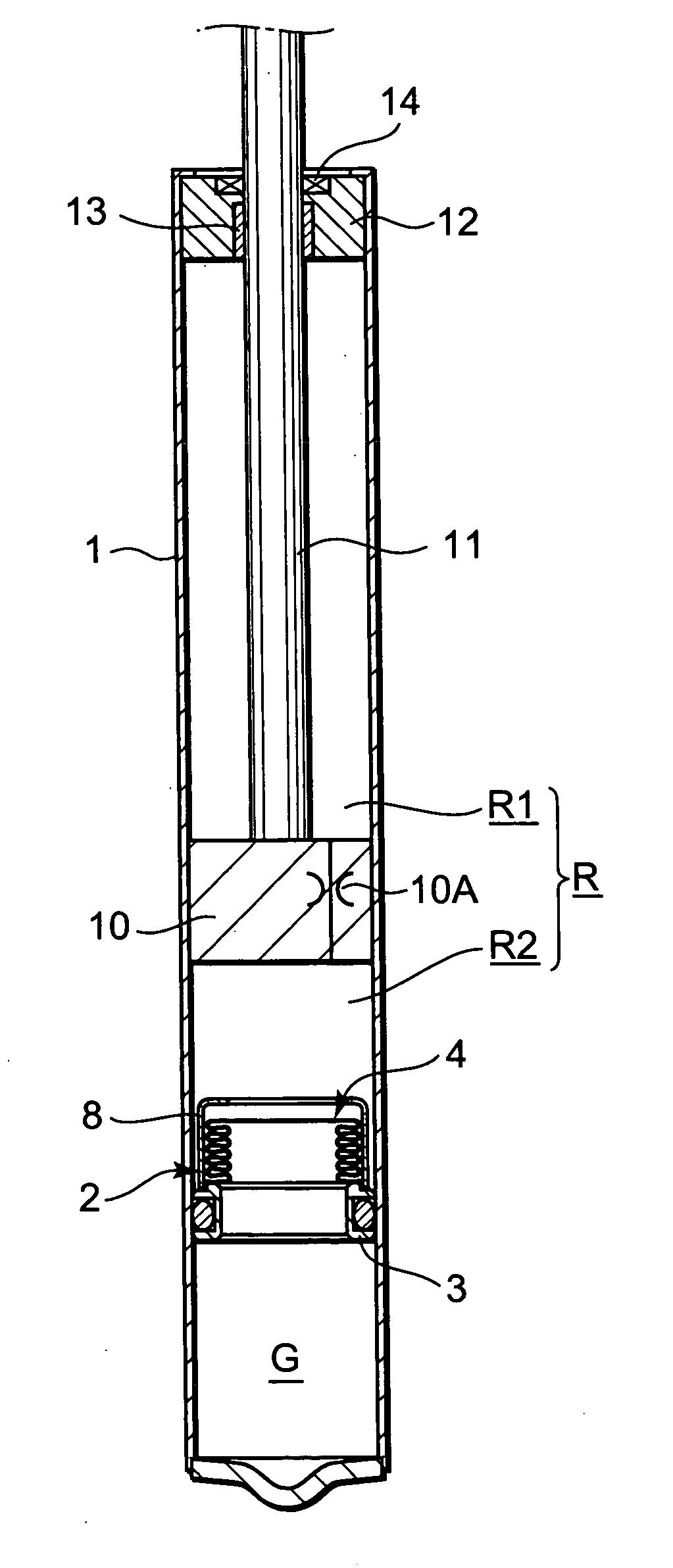
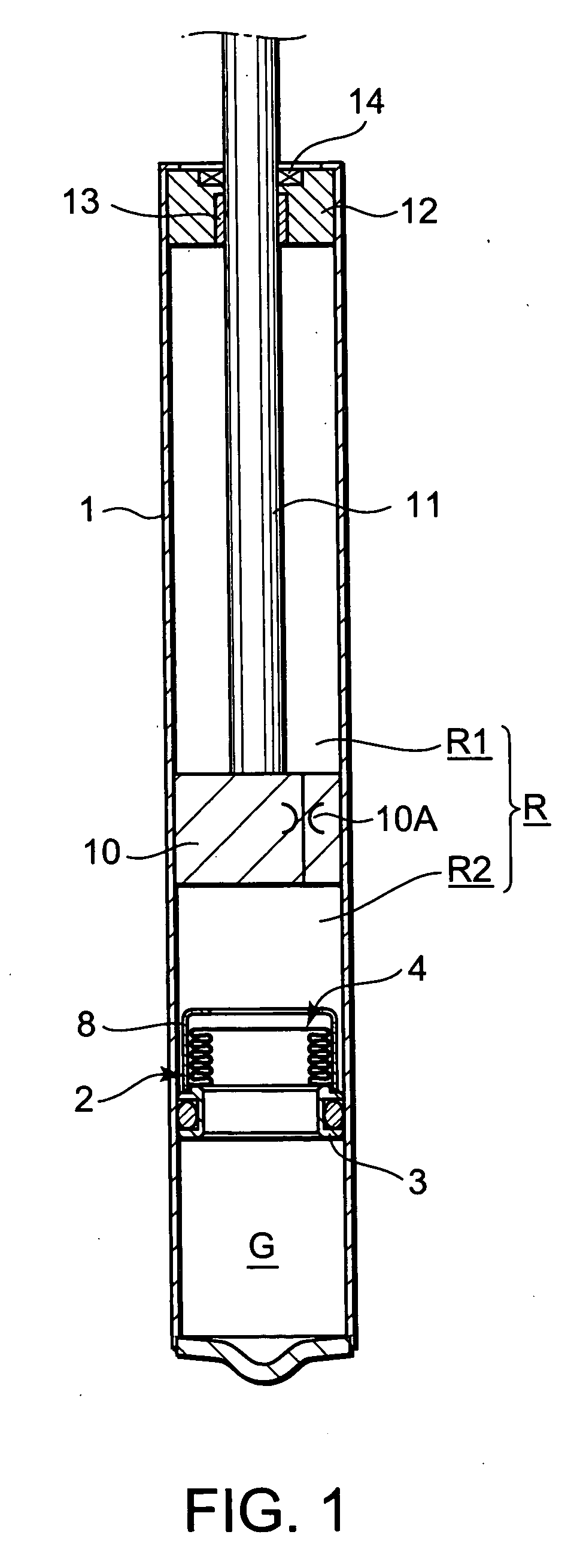
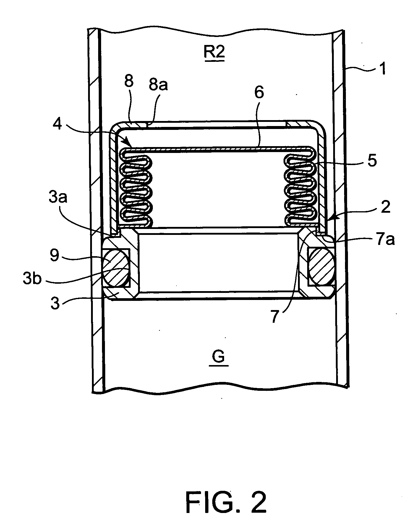
[0015] Referring to FIG. 1 of the drawings, a hydraulic damper comprises a cylinder 1 which constitutes a housing, a free piston 2 which is accommodated in the cylinder 1, a piston 10 which is accommodated in the cylinder 1 above the free piston 2, and a piston rod 11 which is fixed to the piston 10 and projects upward from the cylinder 1. The free piston 2 and the piston 10 are respectively supported so as to be free to slide axially on the inner circumference of the cylinder 1.

[0016] A rod guide 12 is fixed to an upper end of the cylinder 1. The rod guide 12 guides the piston rod 11 in an axial direction while closing the cylinder 1. A bearing 13 for supporting the piston rod 11 and a seal member 14 which is in contact with the piston rod 11 are provided in the rod guide 12. The piston rod 11 is prevented from wobbling with respect to the cylinder 1 by the rod guide 12 and the piston 10.

[0017] The space in the cylinder 1 is divided by the free piston 2 into a lower gas chamber G...


PUM


Abstract

A gas chamber (G) and a liquid chamber (R) are separated by a free piston (2) in a cylinder (1) of a hydraulic damper. The free piston (2) comprises a hollow main body (3), a metal bellows (4) which elongates and contracts according to a pressure balance between the gas chamber (G) and liquid chamber (R), and a stopper (8) fixed to the main body (3) for preventing the metal bellows (4) from elongating beyond a predetermined length. By compensating for variation in the capacity of the liquid chamber (R) caused by a displacement of the piston (10) in the cylinder (1) by elongation or contraction of the metal bellows (4), the damping characteristic of the damper is prevented from becoming unstable due to a frictional force acting on the free piston (2). The stopper (8) prevents excessive stress from being exerted on the metal bellows (4).

Description

FIELD OF THE INVENTION [0001] This invention relates to an improvement of hydraulic equipment having a built-in free piston for separating liquid and gas. BACKGROUND OF THE INVENTION [0002] An accumulator or single tube hydraulic damper has, for example, a free piston which is enclosed in a cylinder or housing so as to be free to slide in order to separate a liquid chamber and a gas chamber. [0003] In an accumulator, temperature variation of the liquid volume in a liquid system is compensated by axial displacement of the free piston in the cylinder so as to increase the capacity of the liquid chamber while decreasing the capacity of the gas chamber, or vice versa. [0004] In a hydraulic damper, variation in the capacity of the liquid chamber due to elongation and contraction of the piston rod is also compensated by the axial displacement of the free piston in the cylinder. [0005] The free piston separating the liquid chamber and gas chamber, is generally provided with a seal member s...

Claims


Application Information

Patent Timeline
IPC IPC(8): F16F9/00
CPCF15B1/103F15B1/24F15B2201/205F15B2201/312F15B2201/3153F16F9/067F16F9/081
Inventor KOJIMA, SHIGERUBABA, TOMOHIKO
Owner KYB CORP
Why Eureka
Try Eureka