Variable speed motor

a variable speed, motor technology, applied in the direction of motor/generator/converter stopper, dynamo-electric gear control, motor/generator/converter stopper, etc., can solve the limitation of varying the limitation of the variable the inability to adjust the speed of the motor, etc., to achieve the effect of greatly reducing the range of a variable speed motor, greatly reducing the electromagnetic vibration noise caused by low-speed motor

Active Publication Date: 2006-08-17
LG ELECTRONICS INC
View PDF16 Cites 28 Cited by
  • Summary
  • Abstract
  • Description
  • Claims
  • Application Information

AI Technical Summary

Benefits of technology

[0023] The variable speed motor performs a switching operation between serial/parallel connections of main and auxiliary windings capable of forming poles, includes a plurality of capacitors connected to the auxiliary winding, greatly extends the range of a variable speed of the motor by controlling capacitances of the capacitors or an input voltage, and varies motor speed in multiple stages within the variable speed range.
[0024] The variable speed motor does not require an additional drive unit for varying the motor speed, such that production costs are greatly reduced, and electromagnetic vibration noise caused by a low-speed control mode of the motor is also greatly reduced.
[0025] The variable speed motor performs a pole-ch...

Problems solved by technology

In this case, if the motor is rotated upon receiving a single-phase AC (Alternating Current) voltage signal, a current variation of the received AC voltage signal is constantly maintained, resulting in limitation in changing speed of the motor.
If the motor includes the above-mentioned additional devices, additional production costs associated with the additiona...

Method used


Image

  • Variable speed motor
  • Variable speed motor
  • Variable speed motor

Examples


Embodiment Construction

[0040] Now, preferred embodiments of the present invention will be described in detail with reference to the annexed drawings. In the drawings, the same or similar elements are denoted by the same reference numerals even though they are depicted in different drawings. In the following description, a detailed description of known functions and configurations incorporated herein will be omitted when it may make the subject matter of the present invention rather unclear.

[0041] A preferred embodiment of the variable speed motor according to the present invention will hereinafter be described with reference to the annexed drawings.

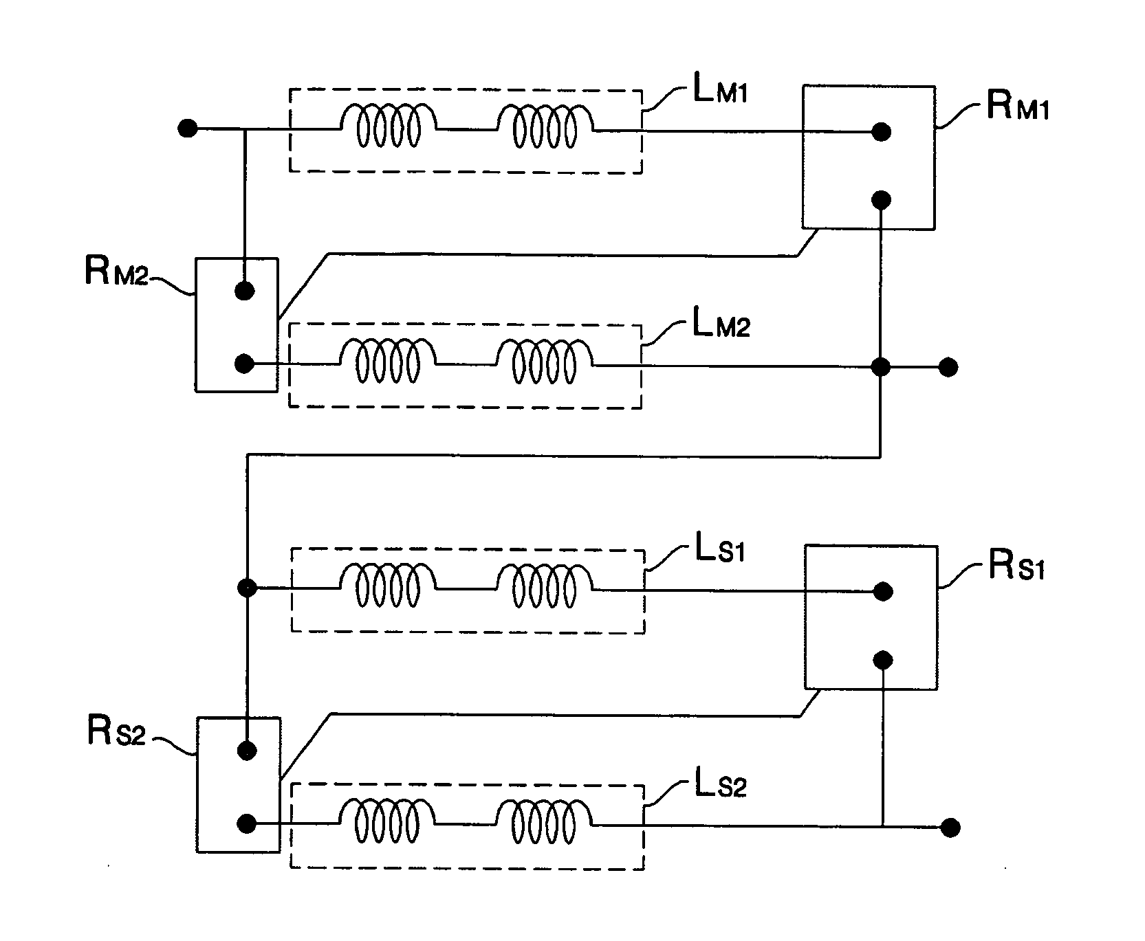
[0042] A variable speed motor according to the present invention is a single-phase induction motor to which a single-phase AC power signal is applied. In the case of an outer-rotation motor in which a rotor is mounted to the outside of a stator, a rotation radius of the outer-rotation motor is greater than that of an inner-rotation motor, and torque per unit ...


PUM


Abstract

A variable speed motor is disclosed. The variable speed motor includes: a main winding including first and second main windings, and an auxiliary winding including first and second auxiliary windings, wherein the main winding and the auxiliary winding are wound on a stator to form a plurality of poles; and a plurality of relays for performing a switching operation between serial/parallel connections of the first and second main windings or the first and second auxiliary windings. The variable speed motor includes: a stator on which a 4-pole winding and a 12-pole winding are wound; a plurality of tap windings connected in series to a 4-pole main winding forming 4 poles, for extending a variable range of rotation speed of the motor during a 4-pole operation mode; and a phase control circuit for varying rotation speed of the motor by controlling a phase of an input power-supply signal during a 12-pole operation mode. Therefore, the variable speed motor greatly extends the range of a variable speed of the motor, and does not require an additional drive unit for varying the motor speed, such that production costs are greatly reduced, and electromagnetic vibration noise caused by a low-speed control mode of the motor is also greatly reduced. Rotation speed of the motor is controlled by a phase control operation and a winding switching operation, such that the variable speed motor effectively controls the motor speed, and greatly reduces power consumption.

Description

BACKGROUND OF THE INVENTION [0001] 1. Field of the Invention [0002] The present invention relates to a variable speed motor, and more particularly to a variable speed motor for allowing a relay to perform a switching operation between serial / parallel connections of at least one winding composed of a main winding and an auxiliary winding, connecting a tap winding to a 4-pole main winding to perform a switching of the tap winding, such that it can greatly increase a variable range of a rotation speed of the motor. [0003] 2. Description of the Related Art [0004]FIG. 1 is an exploded perspective view of a rotor and a stator contained in a conventional outer-rotation motor. FIG. 2 is a circuit diagram of a conventional capacitor-type single-phase induction motor. [0005] Typically, a motor includes a stator to which windings are mounted, and a rotator to which a permanent magnet is mounted. The motor generates periodic current variation in the winding mounted to the stator, torque occurs ...

Claims


Application Information

Patent Timeline
IPC IPC(8): H02P1/42H02K17/08D06F37/36H02P21/04H02P21/05H02P23/00H02P23/03H02P23/04H02P23/07H02P25/04H02P25/10H02P27/02
CPCH02P25/04H02P25/18H02P25/20
Inventor CHOI, BYUNG KEOLLEE, DONG SOOMIN, BYOUNG WOOKKIM, DONG WON
Owner LG ELECTRONICS INC
Why Eureka
Try Eureka