Methods of detecting arc faults characterized by consecutive periods of arcing

Inactive Publication Date: 2006-08-17
SENSATA TECH MASSACHUSETTS INC
View PDF11 Cites 41 Cited by
  • Summary
  • Abstract
  • Description
  • Claims
  • Application Information

AI Technical Summary

Benefits of technology

[0011] By measuring multiple voltage levels provided by the arcing sense circuit during a specified number of consecutive time periods, and analyzing the measured voltage levels based upon criteria such as the number of consecutive periods for which the measured levels exceed a specified minimum value, the numb

Problems solved by technology

In the event the high frequency AC current components resulted from an arc fault, the processing unit activates the firing circuit to trip the electromechanical interface, thereby interrupting the power output to the load.
In this case, the high frequency components of the AC line current are deemed to have resulted from an elect

Method used


Image

  • Methods of detecting arc faults characterized by consecutive periods of arcing
  • Methods of detecting arc faults characterized by consecutive periods of arcing
  • Methods of detecting arc faults characterized by consecutive periods of arcing

Examples


Embodiment Construction

[0028] The entire disclosure of U.S. patent application Ser. No. 10 / 937,487 filed Sep. 9, 2004 entitled METHOD FOR DETECTING ARC FAULTS is incorporated herein by reference.

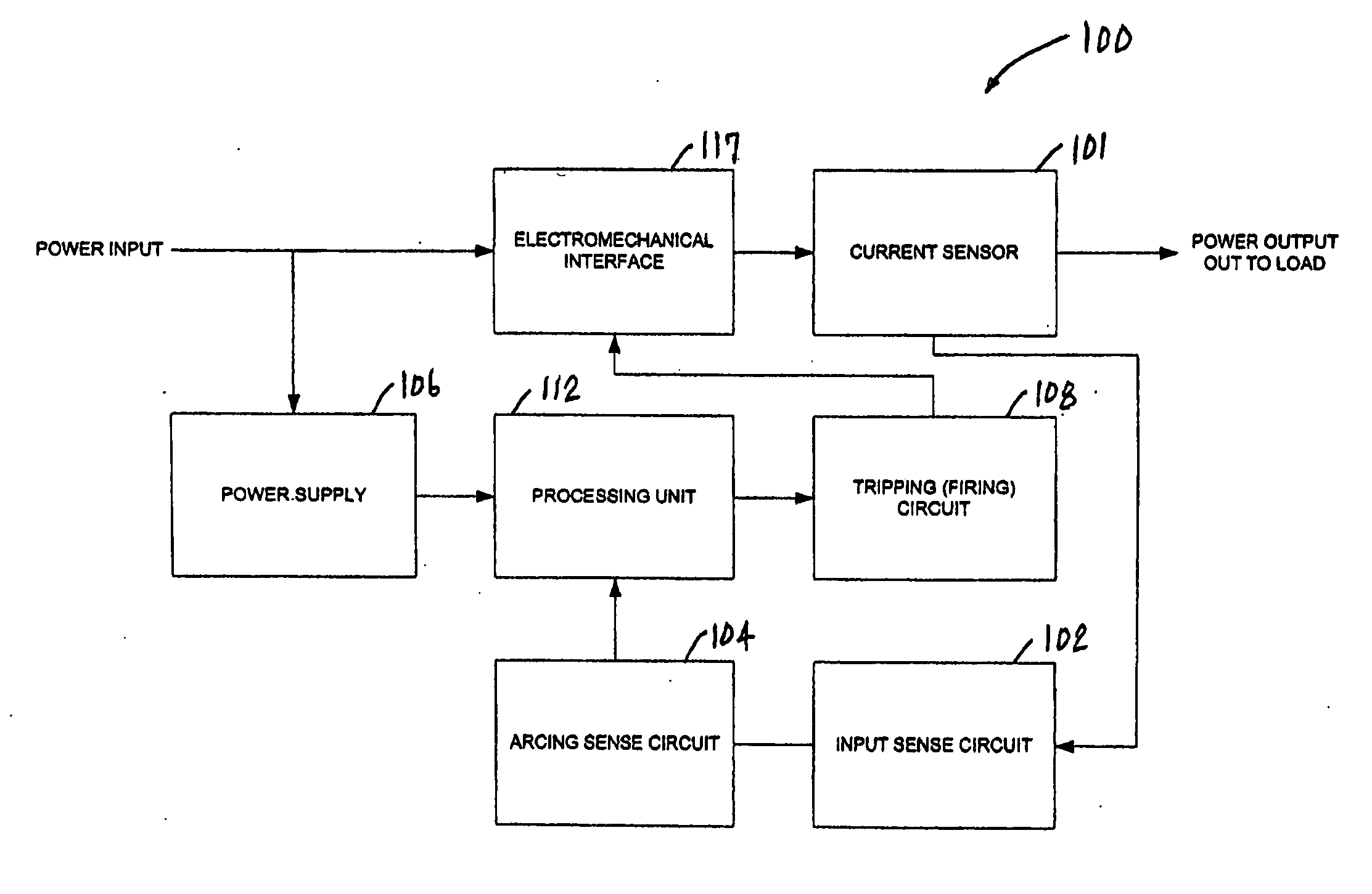
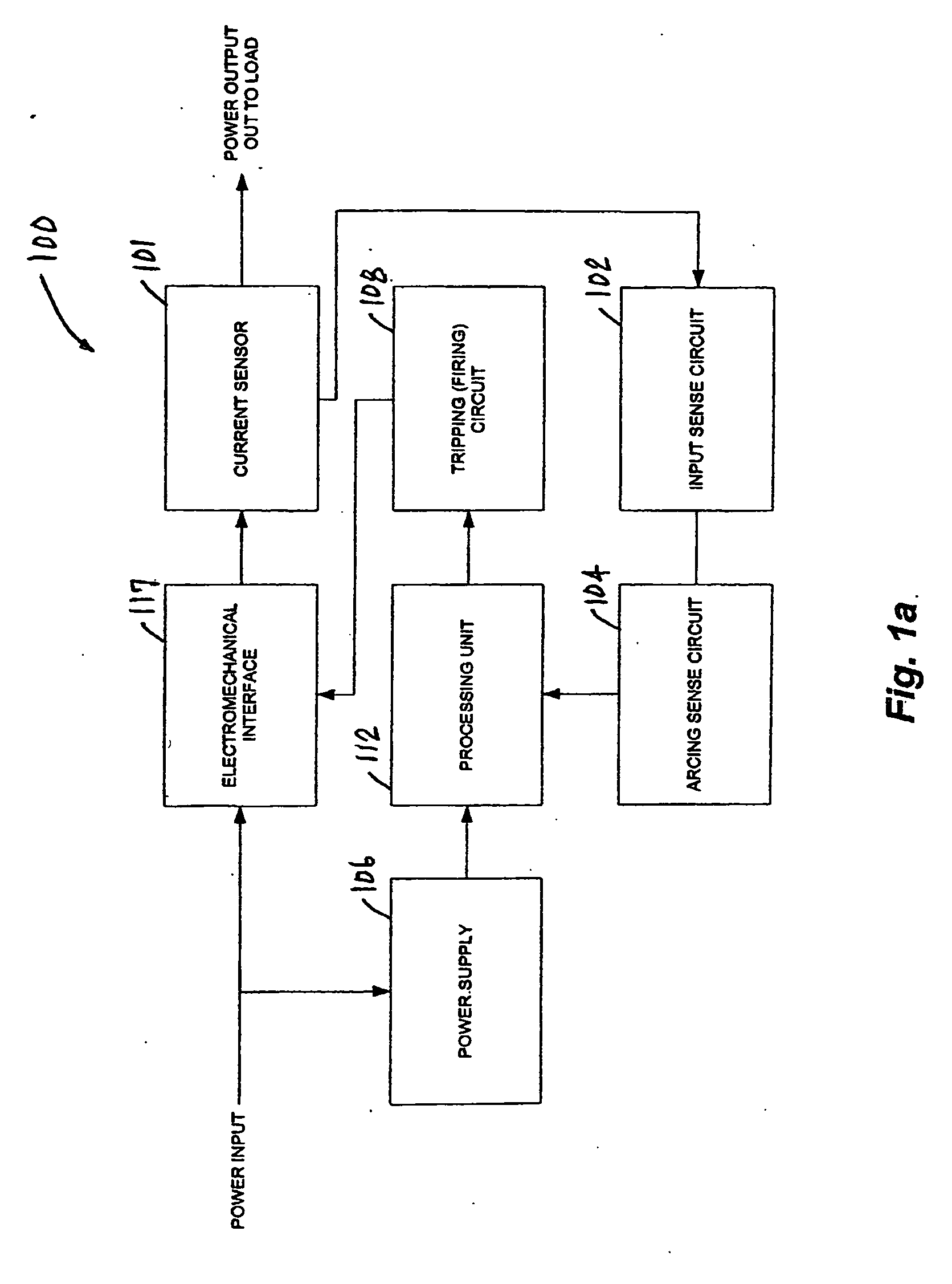
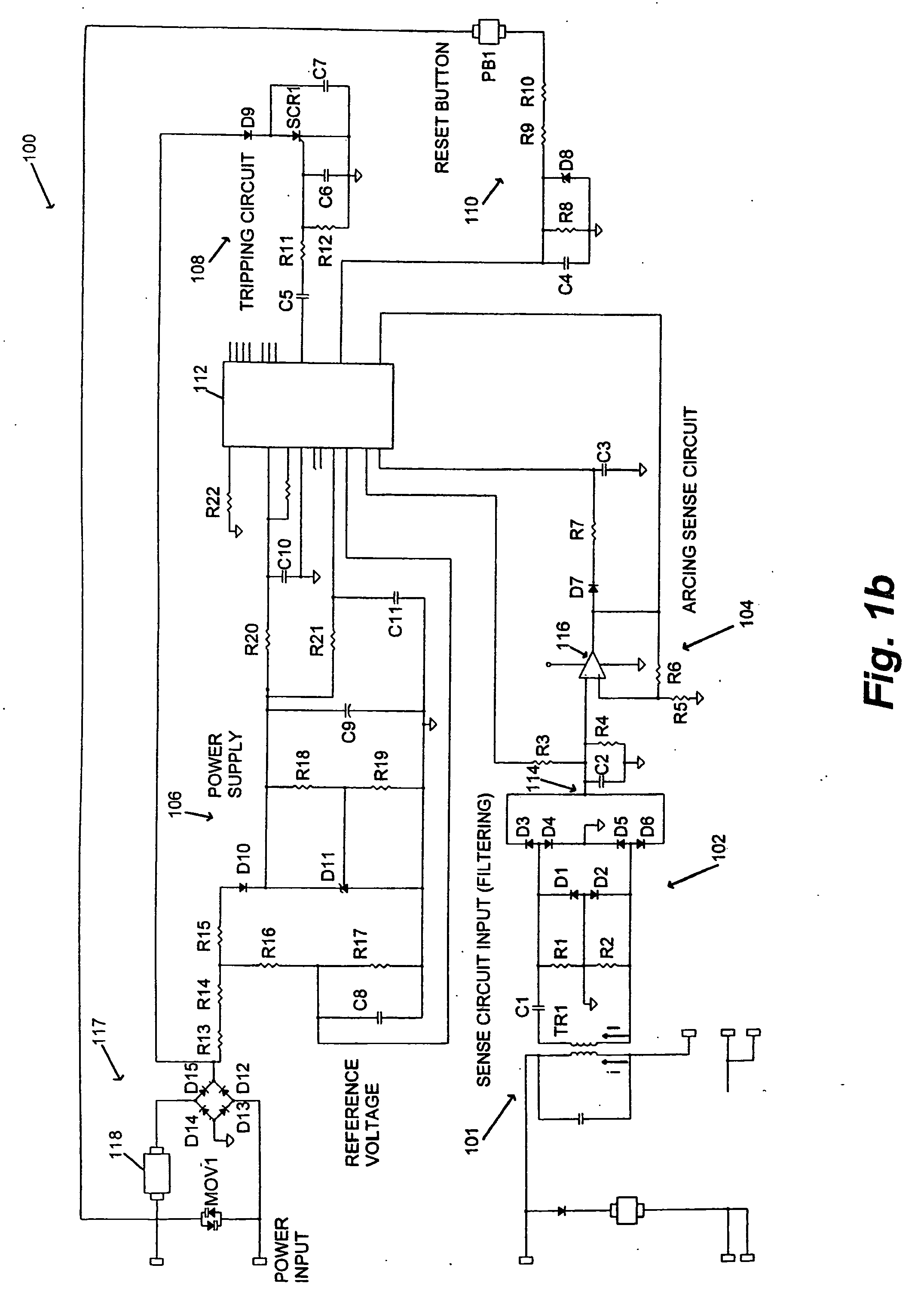
[0029]FIG. 1a depicts an illustrative embodiment of an arc fault detection apparatus 100, in accordance with the present invention. In the illustrated embodiment, the apparatus 100 comprises a current sensor 101, an input sense circuit 102, an arcing sense circuit 104, a power supply 106, a tripping (firing) circuit 108, a processing unit 112, and an electromechanical interface 117. In an illustrative mode of operation, the current sensor 101 monitors a power input via an electromechanical interface 117, and provides high frequency components of the power input to the input sense circuit 102. Next, the input sense circuit 102 filters and rectifies the AC signal at its input, and provides the rectified signal to the arcing sense circuit 104. The arcing sense circuit 104 then provides voltage levels and digital sig...


PUM


Abstract

An apparatus and method for detecting electrical arc faults that has reduced susceptibility to nuisance tripping. The apparatus includes a current sensor, an input sense circuit, an arcing sense circuit, a power supply, a tripping circuit, a processing unit, and an electromechanical interface. The processing unit measures multiple voltage levels provided by the arcing sense circuit during a specified number of consecutive time periods. Next, the processing unit determines the number of consecutive time periods during which the voltage levels exceeded a specified minimum value, take on successively lower or higher values, or fall outside a predetermined normal range of values. Based upon the results of this determination, the processing unit either trips the electromechanical interface to interrupt power to a load, or inhibits tripping of the electromechanical interface, thereby reducing the occurrence of nuisance tripping.

Description

CROSS REFERENCE TO RELATED APPLICATIONS [0001] This application is a continuation-in-part application of prior U.S. patent application Ser. No. 10 / 937,487 filed Sep. 9, 2004 entitled METHOD FOR DETECTING ARC FAULTS.STATEMENT REGARDING FEDERALLY SPONSORED RESEARCH OR DEVELOPMENT [0002] N / A BACKGROUND OF THE INVENTION [0003] The present invention relates generally to apparatus and methods for detecting arc faults, and more specifically to arc fault detection apparatus and methods that are less susceptible to nuisance tripping. [0004] Arc fault detection apparatus and methods are known that employ a micro-controller to measure voltages associated with a load, and to process data representing the voltage measurements to determine the presence of electrical arcing. For example, a conventional arc fault detection apparatus may be configured to sense an alternating load current, to filter and rectify the AC signal, and to provide the rectified signal to an integrating capacitor. The conven...

Claims


Application Information

Patent Timeline
IPC IPC(8): H02H3/00
CPCG01R31/025H02H1/0015H02H1/0092G01R31/52G01R31/12H02H3/08
Inventor PELLON, CHRISTIAN V.LAVADO, MICHAEL J.TING, JEFFREY B.
Owner SENSATA TECH MASSACHUSETTS INC
Why Eureka
Try Eureka