Holographic disk medium with servo marks

Inactive Publication Date: 2006-08-17
THOMSON LICENSING SA
View PDF4 Cites 9 Cited by
  • Summary
  • Abstract
  • Description
  • Claims
  • Application Information

AI Technical Summary

Benefits of technology

[0009] Alternatively, the object and reference beams have a first direction of polarization and the servo beam has a second direction of polarization, the servo marks having a width and a depth adapted to minimize their influence on the object and reference beams. The interaction of small servo marks with a polarized light beam depends strongly on the direction of polarization. By varying the width of a servo marks for a given depth of the servo marks it is possible to minimize thei

Problems solved by technology

This leads to large aberrations of the servo beam, in particula

Method used


Image

  • Holographic disk medium with servo marks
  • Holographic disk medium with servo marks
  • Holographic disk medium with servo marks

Examples


Embodiment Construction

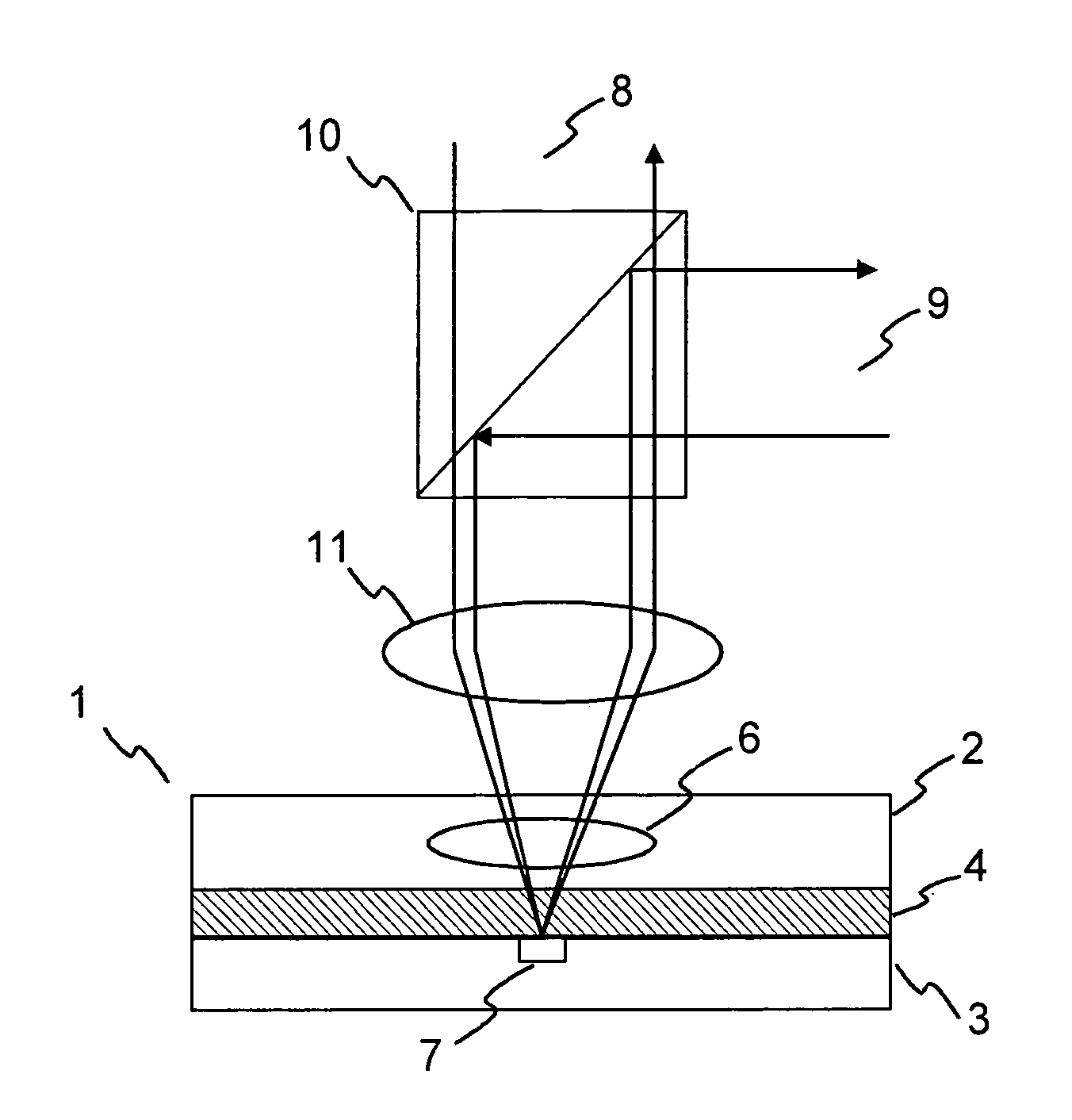
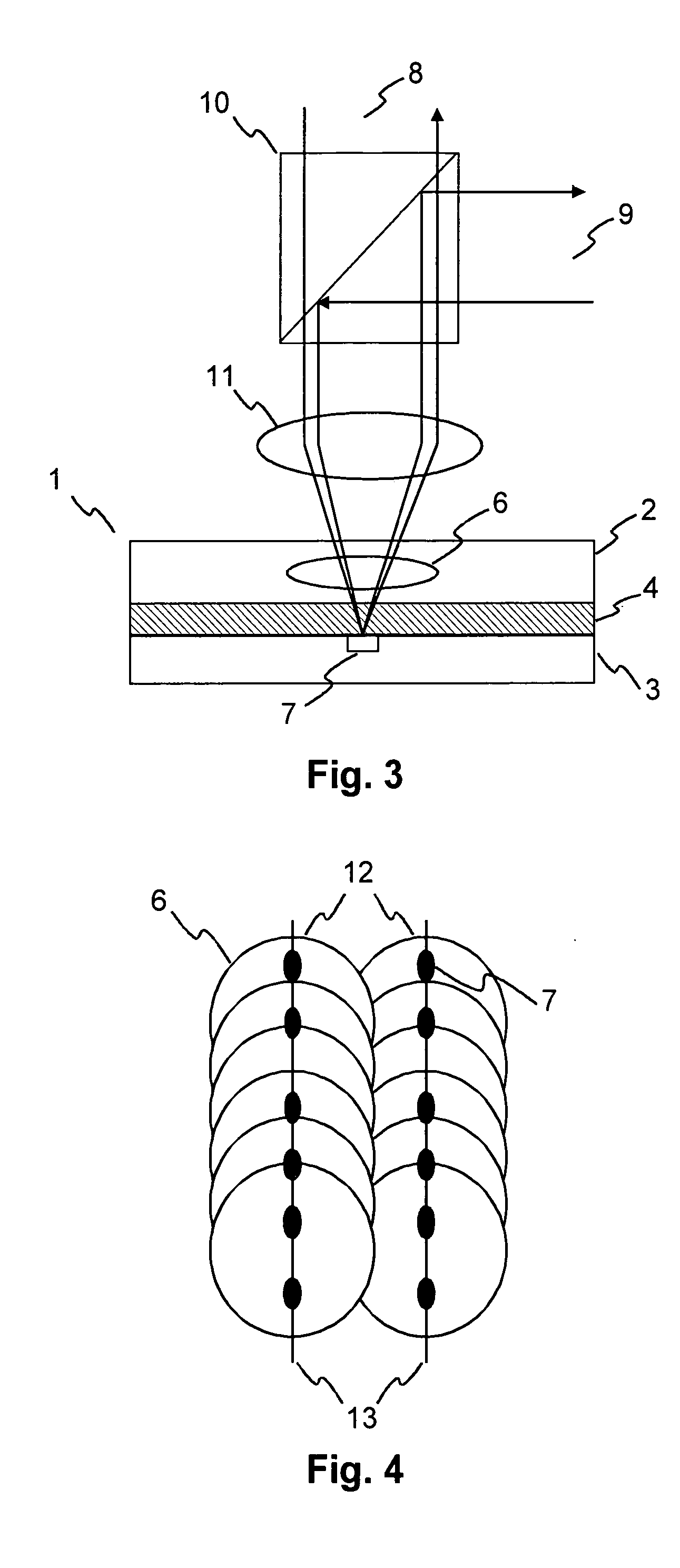
[0017]FIG. 3 depicts a holographic storage system using a holographic disk medium 1 according to the invention. The servo marks 7 (pits or groove) are integrated into the mirror layer 3 and lie directly below the hologram 6 separated by an optional buffer layer 4. Using a buffer layer 4 has the advantage that the holographic material of the recording layer 2 is not recorded in the focus of the focusing lens 11, where the intensity is high and a saturation could occur. However, it is likewise possible to omit the buffer layer 4. The object and reference beams 8 and the servo beam 9 use a similar optical path through the objective lens 11. The servo beam 9 is separated from the object and reference beams 8 by a dichroic beam splitter 10. As the object and reference beams 8 are reflected from the mirror layer 3, the servo marks 7 degrade the holographic write and read process. In order to minimize this degradation, the shape and in particular the depth of the servo marks 7 is chosen in...


PUM


Abstract

The present invention relates to a holographic disk medium (1) with servo marks (7), and more specifically to a holographic disk medium (1) having a common reflective layer (3) for reflecting a servo beam (9) and object and reference beams (8). According to the invention, a holographic disk medium (1) with a recording layer (2) for recording holograms (6) and a reflective layer (3) for reflecting a servo beam (9) and object and reference beams (8), includes servo marks (7) which are located in the reflective layer (3) at least partly below the holograms (6), wherein the servo marks (7) are designed such that their influence on the object and reference beams (8) is minimized.

Description

FIELD OF THE INVENTION [0001] The present invention relates to a holographic disk medium with servo marks, and more specifically to a holographic disk medium having a common reflective layer for reflecting a servo beam and object and reference beams. BACKGROUND OF THE INVENTION [0002] Holographic storage systems are preferably equipped with a servo system to accurately control the position of the optical read / write system relative to a storage medium, e.g. a holographic optical disk. Such a servo system usually makes use of servo marks such as pits located on the storage medium. [0003] It has been proposed to use different laser wavelengths for a servo beam and the object and reference beams. In this case a recording material which is only sensitive to light of one specific wavelength is employed. Light with a different wavelength can then be used for servoing etc. The servo marks are separated from the recording material of the holographic disk medium by a dichroic layer. Such a pr...

Claims


Application Information

Patent Timeline
IPC IPC(8): G11B7/00G11B7/24044
CPCG11B7/0065G11B7/00781G11B7/083G11B7/0938G11B7/24044G11B7/09
Inventor KNITTEL, JOACHIMRICHTER, HARTMUTKNAPPMANN, STEPHAN
Owner THOMSON LICENSING SA
Why Eureka
Try Eureka