Vacuum device and vacuum pump

a vacuum pump and vacuum technology, applied in the direction of machines/engines, liquid fuel engines, positive displacement liquid engines, etc., can solve the problems of large power consumption and increase in and achieve the effect of reducing the manufacturing cost of semiconductor devices and suppressing the power consumption of vacuum pumps

Inactive Publication Date: 2006-08-17
FOUND FOR ADVANCEMENT OF INT SCI
View PDF18 Cites 14 Cited by
  • Summary
  • Abstract
  • Description
  • Claims
  • Application Information

AI Technical Summary

Benefits of technology

[0033] According to the vacuum apparatus or the vacuum pump of this invention, it is possible to suppress the power consumption

Problems solved by technology

Accordingly, in the vacuum apparatus of this type where the number of vacuum pumps used is large, the power consumption increases.
Particularly, since the low

Method used


Image

  • Vacuum device and vacuum pump
  • Vacuum device and vacuum pump
  • Vacuum device and vacuum pump

Examples


embodiment 1

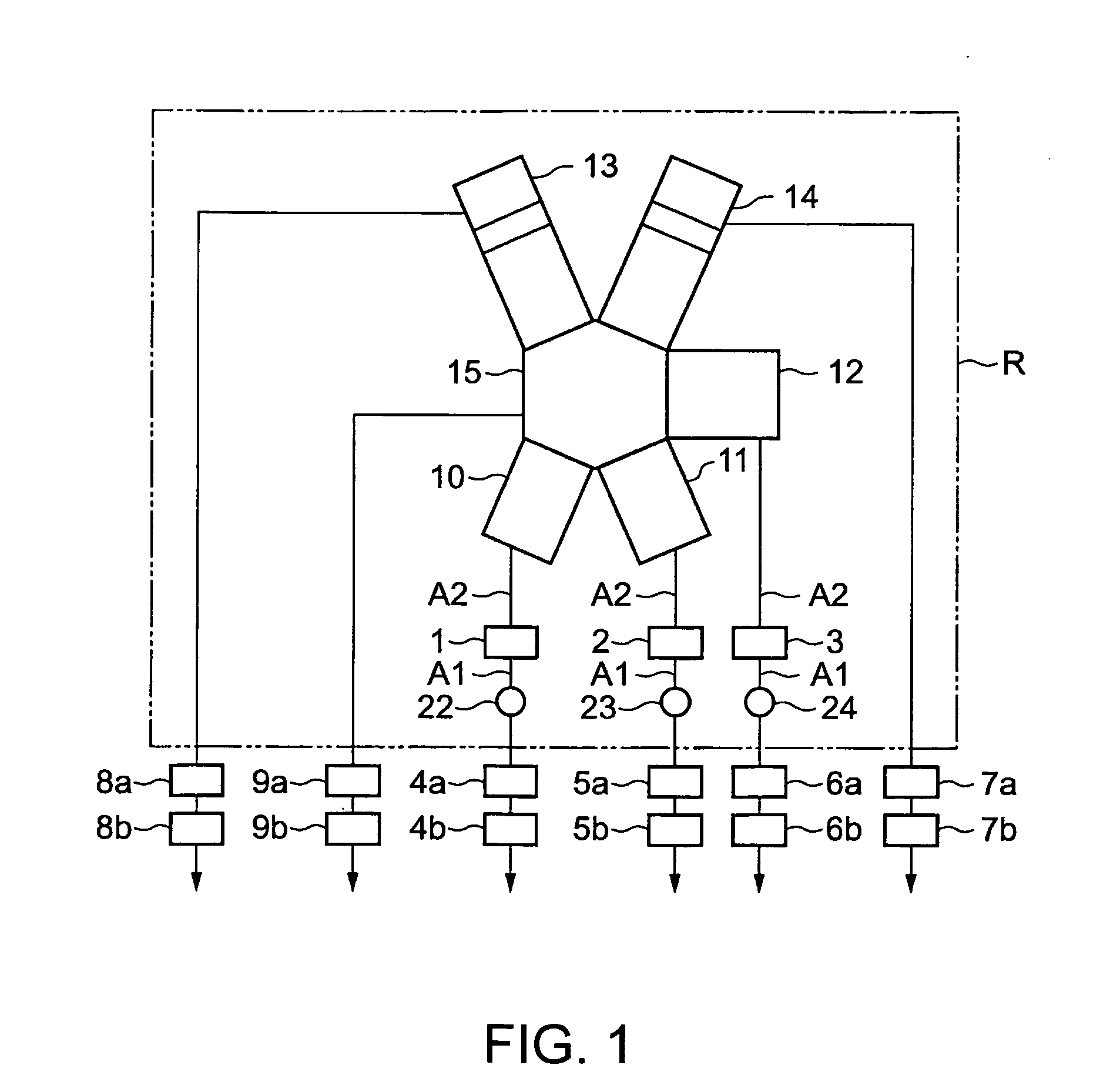
[0042] In the embodiment 1 of this invention, screw pumps A are used as the back pumps 4b, 5b, and 6b in FIG. 1, respectively.

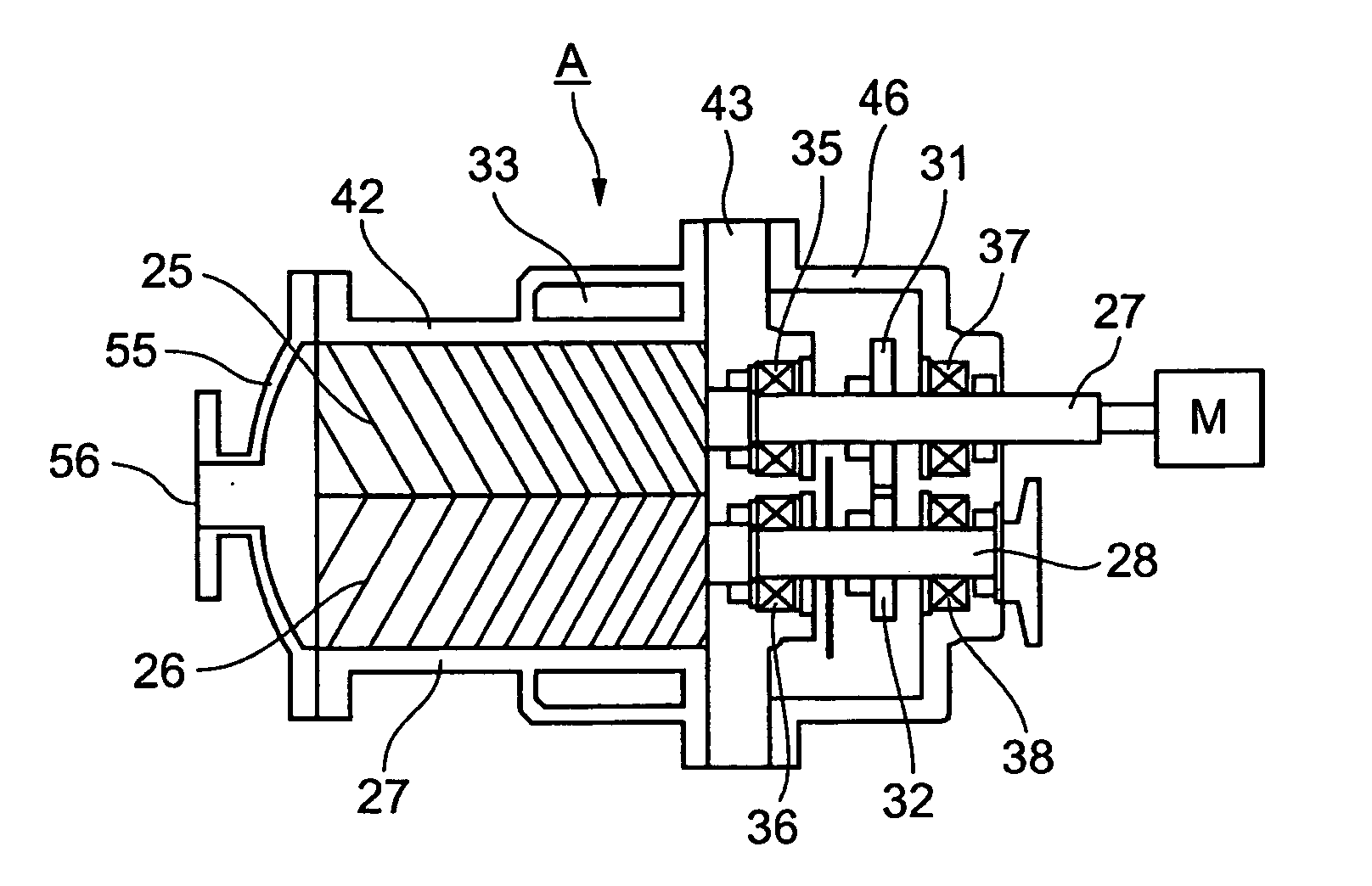
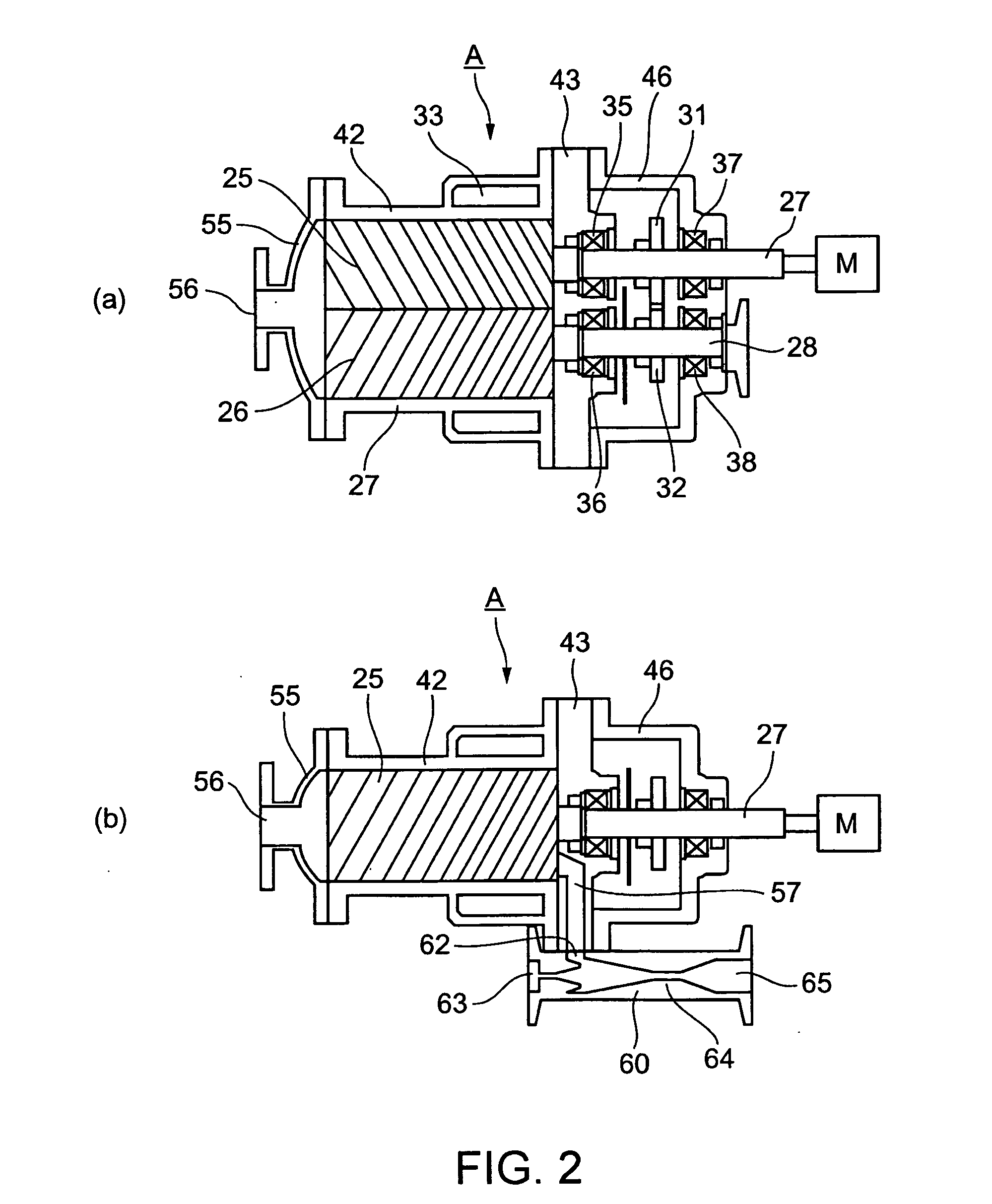
[0043] Referring to FIG. 2,(a) and (b), a male rotor 25 and a female rotor 26 of the screw pump A are received in a main casing 42 and rotatably supported by bearings 35 and 36 attached to an end plate 43 sealing the main casing 42 on its one end side and bearings 37 and 38 attached to an auxiliary casing 46, respectively.

[0044] Timing gears 31 and 32 accommodated in the auxiliary casing 46 are mounted on rotation shafts 27 and 28 of the male and female rotors 25 and 26, respectively, and a gap between the male rotor 25 and the female rotor 26 is adjusted so that both rotors do not contact each other. Further, a motor M is attached to the rotation shaft of the male rotor 25 through a coupling or timing gear. It is configured that the rotation of the motor M is transmitted to the male rotor 25 and rotates the female rotor 26 through the timing gears 31 and 3...

embodiment 2

[0056] In the embodiment 2 of this invention, screw pumps B are used as the back pumps 4b, 5b, and 6b in FIG. 1, respectively.

[0057] Referring to FIG. 4,(a) and (b), in the screw pump B, like in the screw pump A shown in FIG. 2,(a) and (b), a male rotor 25 and a female rotor 26 are received in a main casing 42 and rotatably supported by bearings 35 and 36 attached to an end plate 43 sealing the main casing 42 on its one end side and bearings 37 and 38 attached to an auxiliary casing 46, respectively.

[0058] Timing gears 31 and 32 accommodated in the auxiliary casing 46 are mounted on rotation shafts 27 and 28 of the male and female rotors 25 and 26, respectively, and a gap between the male rotor 25 and the female rotor 26 is adjusted so that both rotors do not contact each other. Further, a motor M is attached to the rotation shaft of the male rotor 25 through a coupling or timing gear. It is configured that the rotation of the motor M is transmitted to the male rotor 25 and rotate...


PUM


Abstract

A vacuum apparatus has a vacuum chamber provided with a gas inlet and a gas outlet, and mechanical vacuum pumps in a plurality of stages for reducing a pressure inside the vacuum chamber and maintaining the pressure-reduced state. The vacuum apparatus has an ejector pump (60) connected to a discharge port (57) of a screw pump (A) as the vacuum pump at the last stage among the vacuum pumps. The vacuum apparatus is reduced in power consumption and used in the semiconductor manufacturing field and so on.

Description

TECHNICAL FIELD [0001] Relating to a vacuum apparatus and, in particular, relating to a vacuum apparatus for use in the semiconductor manufacturing field and so on and a vacuum pump for use in such a vacuum apparatus. BACKGROUND ART [0002] Vacuum apparatuses have been used in the semiconductor manufacturing field and many other industrial fields. The vacuum apparatuses each generally comprise a vacuum chamber and a vacuum pump for keeping the inside of the vacuum chamber in a vacuum or pressure-reduced state. [0003] The vacuum apparatus is disposed in a clean room and is configured to perform predetermined processing while introducing and exhausting a predetermined process gas into and from the vacuum chamber. [0004] Referring to FIG. 1, description will be given of one example of a conventional vacuum apparatus employed in a semiconductor manufacturing system. [0005] This vacuum apparatus comprises a plurality of reaction chambers (vacuum chambers) 10, 11, and 12, high vacuum pumps...

Claims


Application Information

Patent Timeline
IPC IPC(8): F04B23/08F04B37/14F04C18/18F04C18/16F04C23/00F04D19/02F04D19/04F04F5/20F04F5/54
CPCF04B37/14F04C18/16F04C23/005F04C2220/12F04D19/046F04F5/20F04F5/54
Inventor OHMI
Owner FOUND FOR ADVANCEMENT OF INT SCI
Why Eureka
Try Eureka