System and method for global power control

a global power control and transmitter technology, applied in power management, electrical equipment, radio transmission, etc., can solve the problems of significant correlation between the average path loss of the two links, contribute to the background noise on the channel, and have a finite capacity, so as to reduce the requirement of snr for the base station, reduce the maximum transmit power of the mobile station, and reduce the data rate

Inactive Publication Date: 2006-08-17
QUALCOMM INC
View PDF19 Cites 53 Cited by
  • Summary
  • Abstract
  • Description
  • Claims
  • Application Information

AI Technical Summary

Benefits of technology

[0021] The present invention teaches a system and method that globally controls interference in a CDMA system. The method can also be extended to non-CDMA systems, such as Bluetooth and networks compliant with IEEE 802.11 and 802.15. The objective is to control the maximum transmit power from each wireless user such that the interference level at each base station (Node-B) does not exceed a

Problems solved by technology

However, because the forward link and reverse link frequencies are within the same frequency band, a significant correlation between the average path loss of the two links exists.
Although the mobile station randomly chooses a PN time alignment to minimize collisions with other mobile stations that are simultaneously transmitting on the access channel, each additional mobile station transmitting on the access channel contributes to the background noise on the channel, which has a finite capacity.
Unfortunately, the presence of interfering signals within the total power received by the mobile station tends to significantly reduce the accuracy of the mobile station's estimate of path loss.
Similarly, when an inappropriately reduced estimate of path loss results in an overly favorable indication of channel quality being provided to a user, the user may be unsuccessful at initiating communication over the degraded channel.
Additionally, the inaccurate estimate of path loss may lead to the mobile station sending out initially weaker access probes, resulting in multiple unsuccessful attempts to establish communi

Method used


Image

  • System and method for global power control
  • System and method for global power control
  • System and method for global power control

Examples


Embodiment Construction

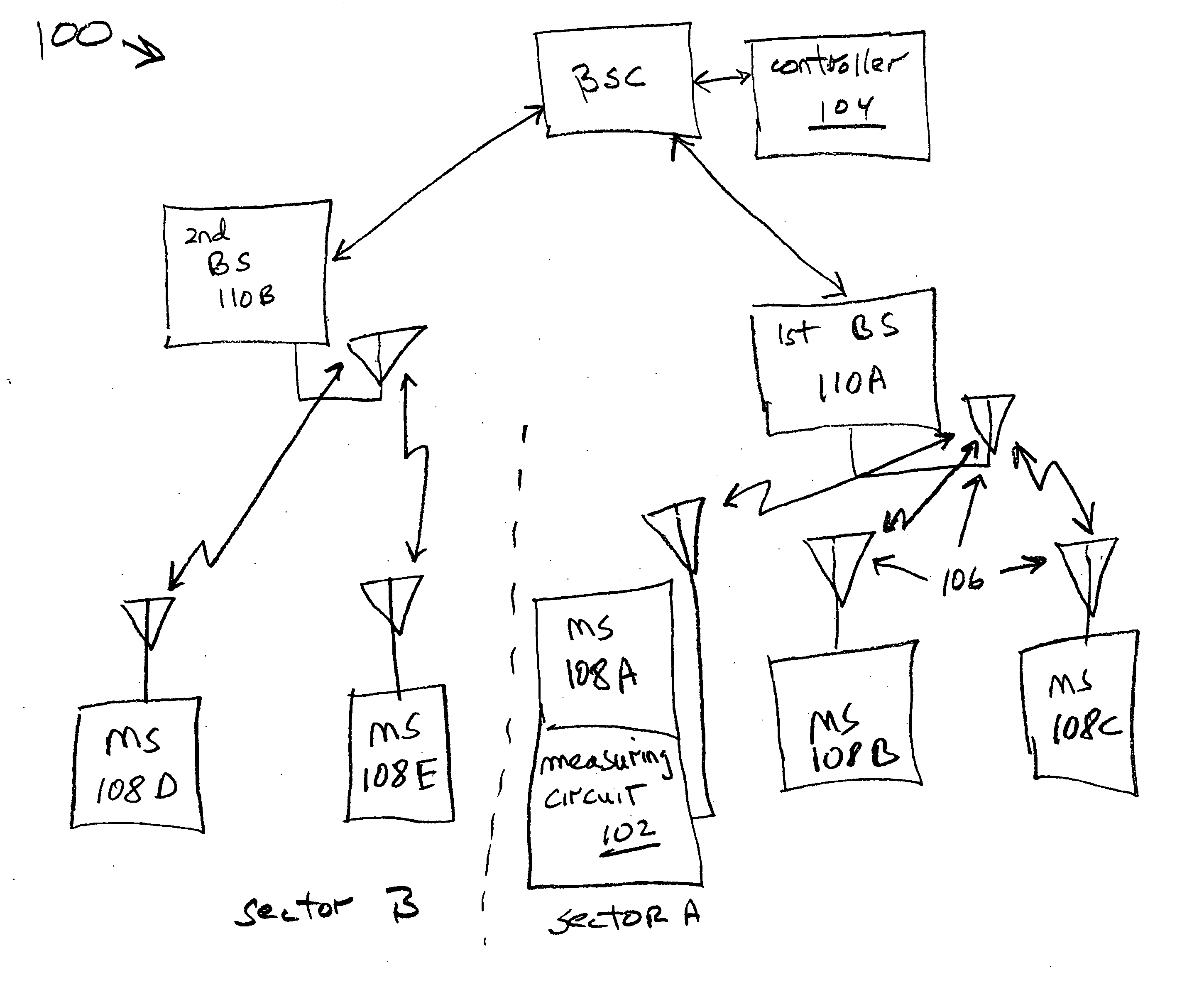
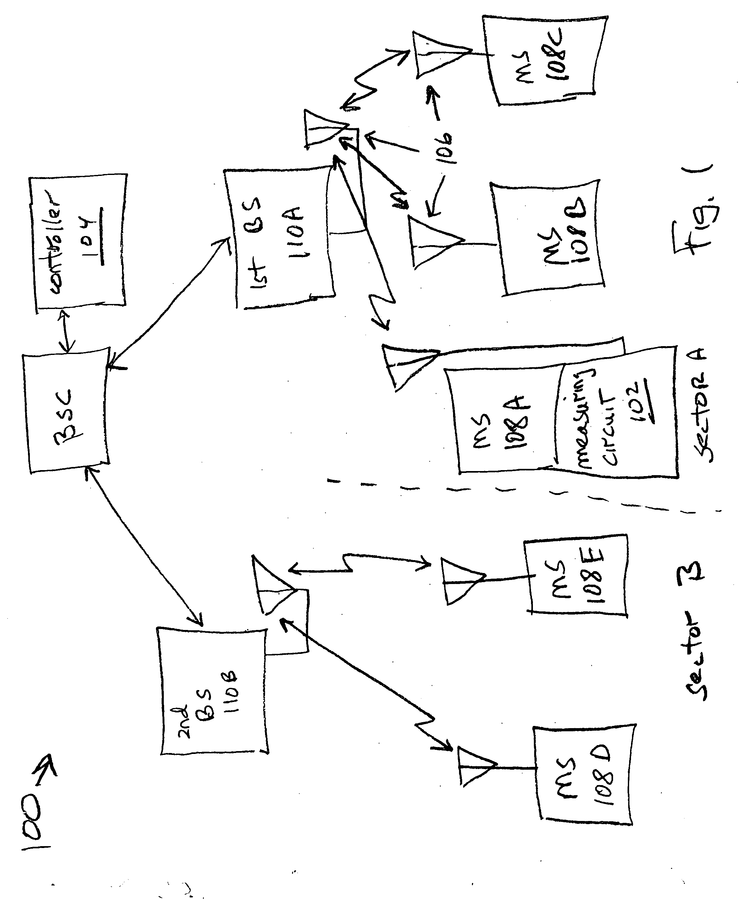
[0038]FIG. 1 is a schematic block diagram of a system for global transmission power control in a wireless communication device. The system 100 comprises wireless communications receiving devices. Each receiving device includes an air interface 106, and may also include a measurement circuit 102 for measuring received power. That is, the radio frequency (RF) power within a particular channel or frequency span is measured. This received power measurement includes the transmitted signals of intended communication partners as well as “interference”. This interference may include the transmission signals of other devices sharing the channel (frequency span), harmonics and spurious signals generated in other channels, and thermal noise. Note, although only a single measure circuit is shown (embedded with mobile station 108A), a measurement circuit 102 may be embedded with each receiving device in the system.

[0039] A controller 104 has an interface connected to the receiving devices for c...


PUM


Abstract

A system and method are provided for global transmission power control in a wireless communication device. The method comprises: measuring the received power of a receiving device; collecting the received power measurements, and accepting a received power threshold; and, generating the optimal transmit power level for a transmitting device, in response to the collected received power measurements and received power threshold. The received power measurements of base station can be collected and the method generates the optimal transmit power level for a mobile station in response to the collected base station received power measurements. Alternately, the received power for mobile stations in a network downlink can be measured and collected, and the optimal transmit power level for a base station can be calculated in response to the collected mobile station received power measurements.

Description

BACKGROUND OF THE INVENTION [0001] 1. Field of the Invention [0002] This invention generally relates to wireless communication systems and, more particularly, to a system and method for globally controlling transmitter power levels in a wireless communications network. [0003] 2. Description of the Related Art [0004] In a Code Division Multiple Access (CDMA) cellular telephone system, such as that described in Telecommunications Industry Association (TIA) / Electronic Industries Association (EIA) Interim Standard 95 (IS-95) entitled “Mobile Station-Base Station Compatibility Standard for Dual-Mode Wideband Spread Spectrum Cellular System,” a common frequency band is used for communication with all base stations in a system. The common frequency band allows simultaneously communication between a mobile station and more than one base station. Signals occupying the common frequency band are discriminated at the receiving station through the spread spectrum CDMA waveform properties based o...

Claims


Application Information

Patent Timeline
IPC IPC(8): H04B7/00H04Q7/20H04W52/24H04W52/34
CPCH04W52/143H04W52/146H04W52/24H04W52/242H04W52/245H04W52/346H04W52/386H04W24/00
Inventor SOLIMAN, SAMIR S.
Owner QUALCOMM INC
Why Eureka
Try Eureka