Apparatus, system and method for optically analyzing a substrate

a substrate and optical analysis technology, applied in the field of apparatus, system and method for optical analysis of substrates, can solve the problem of colorectal cancer survival rate not as encouraging

Inactive Publication Date: 2006-08-17
INNEROPTIC TECH
View PDF6 Cites 386 Cited by
  • Summary
  • Abstract
  • Description
  • Claims
  • Application Information

AI Technical Summary

Benefits of technology

[0028] In a preferred embodiment, the system includes multiple imaging devices and one or more utilities programmed to geometrically register the geometry of the substrate to the pixels of the multiple imaging devices and/or normalize intensity values across multiple images of the substrate from the multiple imaging devices. In certain embodiments, the normalization is accomplished automatically. The normalization may be based on an area of said imagery selected by input from a user. The system may include a utility programmed to extract subsections of said substrate wherein one or both of excessive light intensity or insufficient light intensity prevents imaging of said substrate with sufficient quality to permit the desired analysis. For example, the utility may be programmed to omit such subsections from diagnostic processing and/or to inform the user that said subsections will require re-imaging during one or more of adjusted lighting, filtering, or positioning circumstances. The system may include a utility programmed to identify spectral attributes in image sub-areas characteristic to a tissue abnormality or not characteristic of normal tissue and provide output to a user indicating the location of such image sub-areas. The analysis and output may include classification of the tissue abnormality.
[0029] The output may, for example, include a visible color image of said substrate displayed on a user interface; and one or more indicators displayed on the user interface pointing out, circumscribing or highlighting any image sub-areas having spectral attributes characteristic of a tissue abnormality or not characteristic of normal tissue. The output may, for example, include a visible color image of said substrate displayed on a user interface, and one or more indicators displayed on the user interface pointing out, circumscribing or highlighting any image sub-areas having spectral attributes characteristic of a tissue abnormality or not characteristic of normal tissue, and textual or symbolic information displayed on the user interface communicating information relating to classifying the tissue abnormality. The output may include a visible, monochromatic or color image of the tissue substrate, and textual or symbolic information communicating information of relevance to diagnosis or tre

Problems solved by technology

However, trends in survival rates for co

Method used


Image

  • Apparatus, system and method for optically analyzing a substrate
  • Apparatus, system and method for optically analyzing a substrate
  • Apparatus, system and method for optically analyzing a substrate

Examples


embodiment 1

7.1.1 Embodiment 1

[0252] In this embodiment, the system is designed to detect cervical pre-cancers and cancers. Several wavelengths of interest are known in the art and thus have already been identified for inclusion into such a system: 420 nm [GEOR02, MIRA02], 500 nm [NORD01], 849 nm [HORN99], 956 nm [HORN99], and 1450 nm [ALI04].

[0253] The MWIOS 500 can be constructed with five interference filters 502 for isolating and imaging the wavelengths of interest. The wavelengths of interest can be transmitted to an image processing pipeline, which will determine the optical properties of the target substrate. The system can be calibrated using tissue phantoms (as explained below in Section 7.2), and on in vitro tissue samples (as explained below in Section 7.3).

[0254] Two optical paths for the MWIOS are now described.

[0255] Referring now to FIG. 9, this embodiment depicts an MWIOS prototype 900, which generally includes the following components for analysis of a tissue phantom or in v...

embodiment 2

7.1.2 Embodiment 2

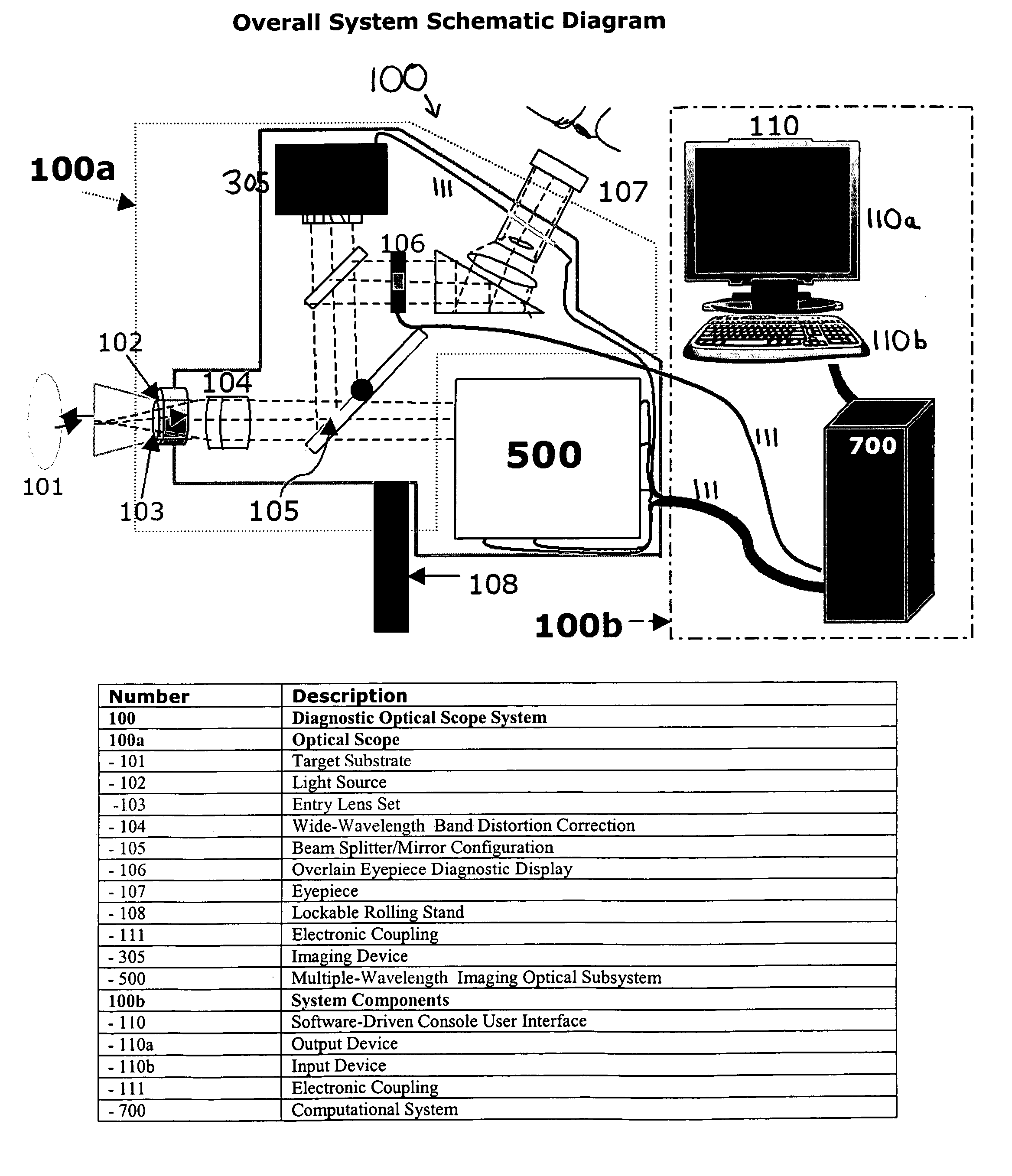
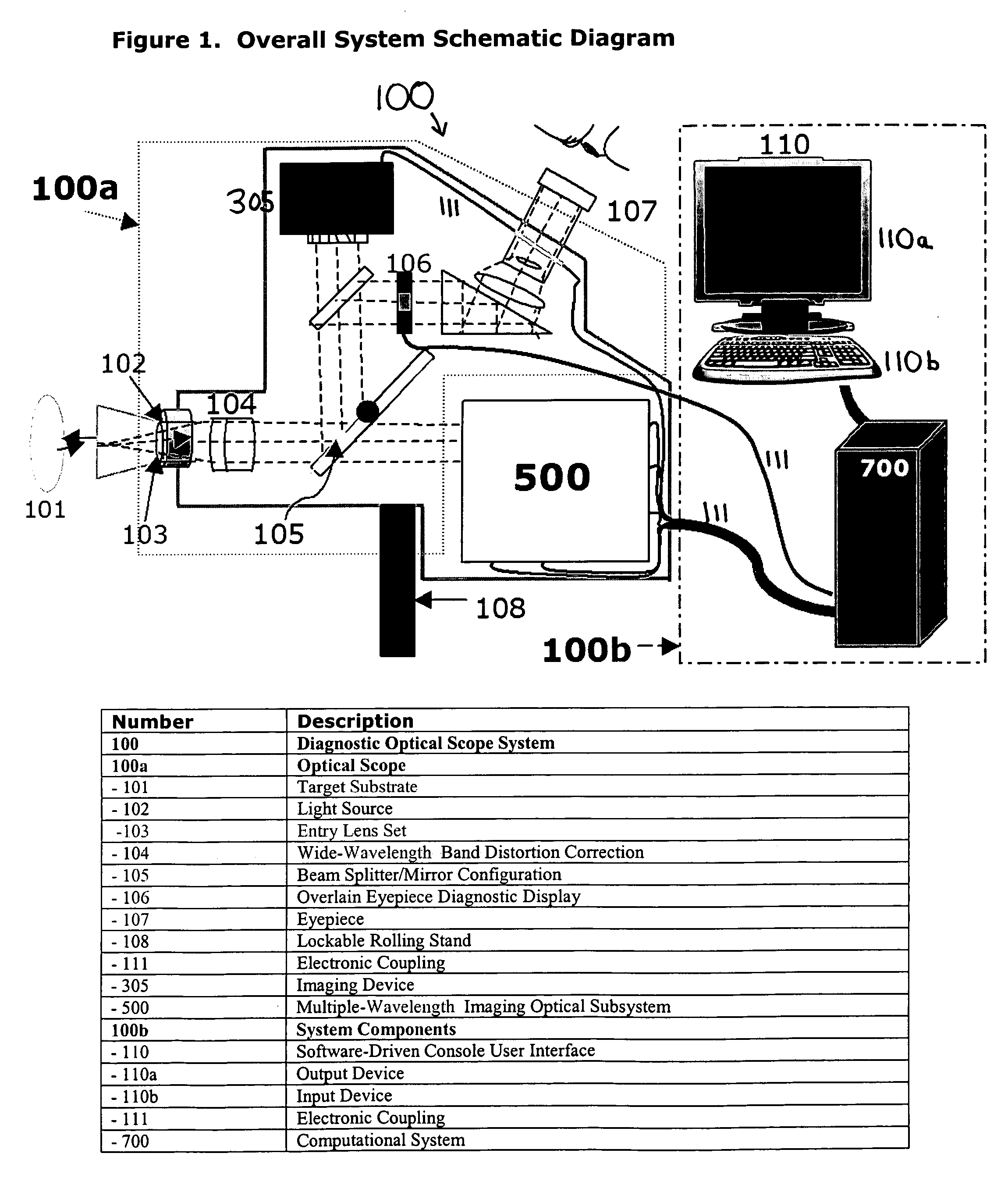
[0286] This embodiment is based on the schematic presented in FIG. 1. A standard colposcope, based on well-established colposcopic optical diagrams, can be constructed, into which all ancillary components associated with the invention can be integrated. The entrance portion of the optical path will be similar to the MWIOS described in Section 7.1.1, including a light source 102, a tissue target 101, an entry lens 103, 302 and an achromatic lens 104 for wide-band distortion correction. In this embodiment, in order to accommodate backward compatibility to a conventional optical scope, the full-system's optical path must include a BS / MC 105 after the entry lens set 103, 302.

[0287] The MWIOS 500 of this embodiment may include of four high-quality NIR-optimized CCD cameras, to individually image the 420-nm, 500-nm, 849-nm and 956-nm wavelengths, and one InGaAs camera, to image the 1450-nm wavelength. While the images at 849 nm and 956 nm would perhaps be better served ...


PUM


Abstract

An apparatus for optically analyzing a substrate. The apparatus includes: (a) a light source for directing light onto the substrate; (b) optics for creating an optical path from light reflected from the substrate; and (c) a multiple wavelength imaging optical subsystem positioned in the optical path. The multiple wavelength imaging optical subsystem includes: (i) one or more filters which are capable of one or both of: (1) being alternatively or sequentially interposed in the optical path to extract one or more of wavelengths or wavelength bands of interest; or (2) having their wavelength selectivity adjusted to extract one or more wavelengths or wavelength bands of interest; and (ii) one or more imaging devices positioned to image the extracted wavelengths or wavelength bands of interest from the one or more filters; (d) an imaging device positioned in the optical path. Also a method is included, making use of the apparatus for analysis of a substrate.

Description

[0001] The present application is based on and claims priority to Provisional U.S. patent application Ser. No. 60 / 634,510, entitled “Optical Detection and Classification of Pre-Cancers and Cancers via Endoscopes, Colposcopes, and Optical Systems,” filed on Dec. 9, 2004 by Kurtis Keller et al.1 Field of the Invention [0002] The present invention relates to an apparatus, system and method for optically analyzing a substrate. The invention also relates to a multiple wavelength-imaging optical subsystem (MWIOS) for use in an apparatus of the invention. Further, the invention relates to optical scopes, such as diagnostic scopes, which include the MWIOS, and to optical scope systems which may also include light emitting, collecting, and analysis capability for analysis and / or diagnosis of tissue abnormalities, particularly human tissue abnormalities. The invention also relates to methods of using the apparatus, system and method of the invention in the analysis of a substrate, such as a t...

Claims


Application Information

Patent Timeline
IPC IPC(8): A61B6/00
CPCA61B5/0059A61B5/0086A61B5/14532A61B5/445G01N21/47
Inventor KELLER, KURTIS PIERCEGREEN, CAROLINE KELLYSTATE, ANDREIWAX, ADAM
Owner INNEROPTIC TECH
Why Eureka
Try Eureka