Self-molding annuloplasty ring

a technology of annuloplasty and self-molding, which is applied in the field of self-molding annuloplasty rings, can solve the problems of affecting the heart's function, affecting the efficiency of implantation surgery, and reducing the effect of implantation surgery

Inactive Publication Date: 2006-08-17
MARQUEZ SALVADOR
View PDF39 Cites 74 Cited by
  • Summary
  • Abstract
  • Description
  • Claims
  • Application Information

AI Technical Summary

Benefits of technology

[0008] The present invention solves the aforementioned problems in that the resilient annuloplasty ring of the present invention may be stretched to the diameter of the dilated valve annulus prior to implantation, thereby simplifying the implantation process. In addition, the contractive force of the resilient annuloplasty ring of the present invention may controllably reduce the diameter of an incompetent dilated valve annulus to more competent diameter. Those skilled in the art will appreciate the present invention is easy to manufacture and may be manufactured from a plurality of materials.
[0011] In yet another embodiment of the present invention, a self molding annuloplasty ring having a predetermined contracted diameter is disclosed. This embodiment comprises a resilient inner sizing member positioned within a series of individual support members. A flexible outer attachment sheath is positioned on the exterior of the support members. This embodiment permits the surgeon to predetermine the inner diameter of a repaired valve annulus, thereby rendering an incompetent valve competent. Those skilled in the art will appreciate that the support members may be manufactured from a biologically compatible material such as, without limitation, plastic and elastomer.

Problems solved by technology

One common example of valvular dysfunction occurs when the annulus becomes excessively dilated or the valve geometry results in ineffective valve closure, which results in regurgitation.
Due to the increased diameter of the annulus, the leaflets or cusps fail to meet during systolic contraction, thereby resulting in the regurgitation of blood during ventricular contractions.
The implantation of a rigid annuloplasty ring restricts the natural flexibility of this tissue, and may impact the heart's function.
Also, the diameter of the dilated annulus is substantially larger than the annuloplasty ring, thereby making the implantation surgery unnecessarily time consuming.
Consequently, the sutures may be under different stress loads, and could result in an increased risk of ring dehiscence.

Method used


Image

  • Self-molding annuloplasty ring
  • Self-molding annuloplasty ring
  • Self-molding annuloplasty ring

Examples


Embodiment Construction

[0027] The following detailed description and the accompanying drawings are intended to describe and show certain presently preferred embodiments of the present invention, and are not intended to limit the scope of the invention in any way.

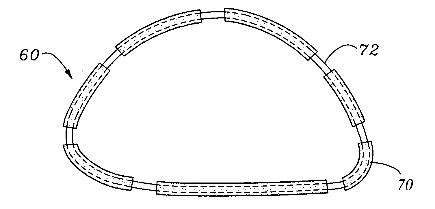
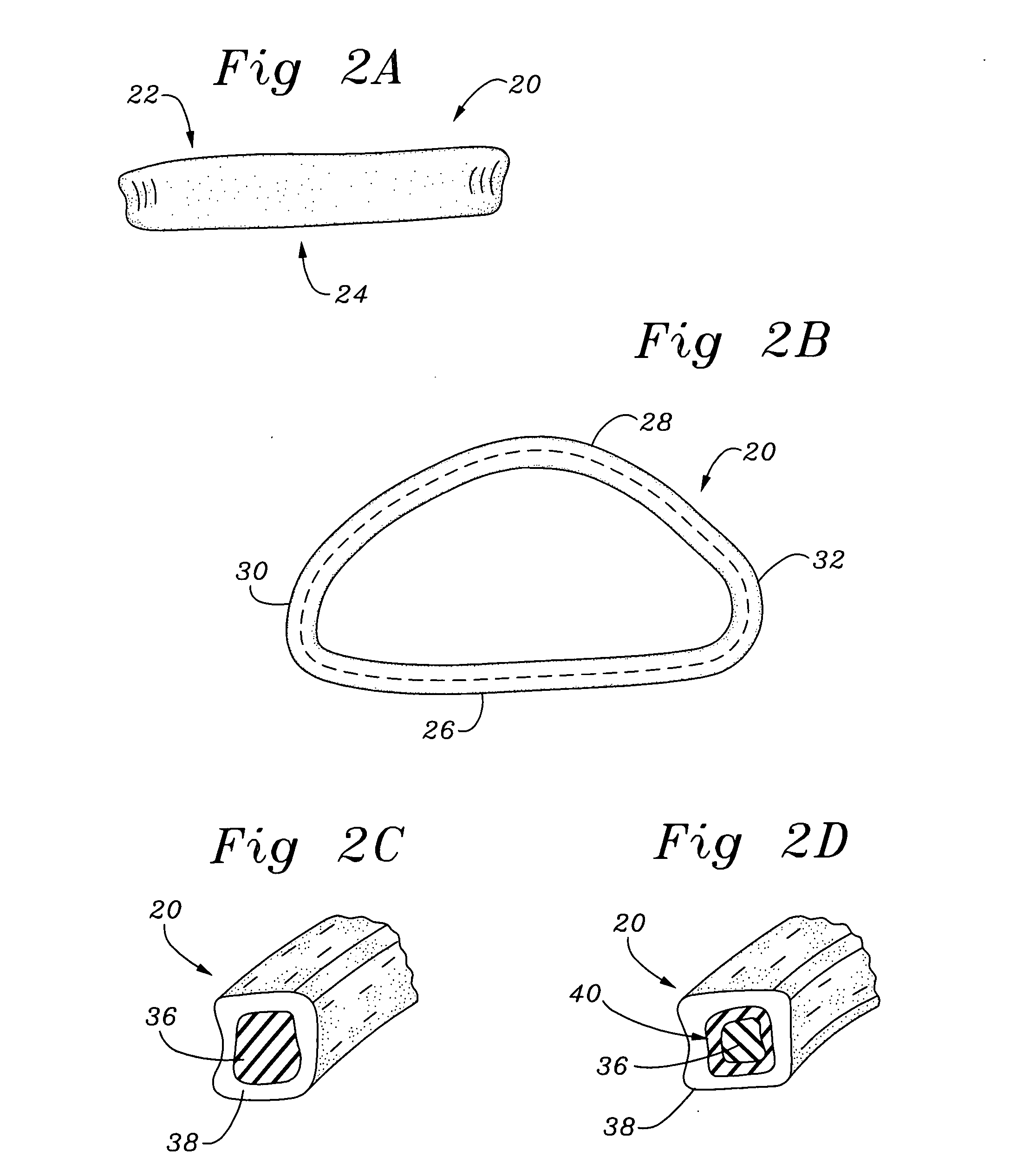
[0028] The self-molding annuloplasty ring of the present invention is generally used in surgical procedures to repair an incompetent tissue annulus. More specifically, the present invention is used to render an otherwise incompetent heart valve competent by decreasing the diameter of the opening at the valvular junction. As those skilled in the art will appreciate, the present invention may be manufactured with varying degrees of pre-tension and contractive force, thereby permitting variations of the contraction of the anterior and / or posterior annuli. In addition, the present invention simplifies the implantation procedure by permitting pre-stretching of the annuloplasty ring to the diameter of the dilated annulus, and thereafter reducing the an...


PUM


Abstract

A resilient self molding annuloplasty ring which may be enlarged prior to implantation to facilitate implantation within a dilated or otherwise incompetent valve annulus having sufficient contractive force to render a valve competent. The self-molding annuloplasty ring may further comprise integral attachment devices to aid in the implantation process. The resilient self-molding annuloplasty ring may be stretched to an expanded diameter and attached to a heart valve annulus, then permitted to contract to reduce the diameter of the annulus. The ring may be positioned on an insertion device that maintains the ring in its expanded diameter while attaching to the annulus.

Description

RELATED APPLICATIONS [0001] The present application is a continuation of Ser. No. 10 / 777,343, filed Feb. 12, 2004, entitled METHOD OF IMPLANTING A SELF-MOLDING ANNULOPLASTY RING, which is a continuation of Ser. No. 09 / 938,902, filed Aug. 24, 2001, entitled SELF-MOLDING ANNULOPLASTY RING, now U.S. Pat. No. 6,726,716, which applications are expressly incorporated herein by reference.BACKGROUND OF THE INVENTION [0002] The human heart is hollow muscular organ having four pumping chambers separated by four heart valves. The mitral and tricuspid valves, present at the left and right atrio-ventricular junctions, open and close in response to a pressure gradient during each cardiac cycle of relaxation and contraction to control the flow of blood to a particular region of the heart. [0003] These valves are comprised of a dense fibrous ring known as the annulus, leaflets or cusps attached to the annulus, and a complex of chordae tendineae and papillary muscles securing the leaflets. The size ...

Claims


Application Information

Patent Timeline
Patent Type & Authority Applications(United States)
IPC IPC(8): A61F2/24
CPCA61F2/2445A61F2/2448Y10S623/902
Inventor MARQUEZ, SALVADOR
Owner MARQUEZ SALVADOR
Why Eureka
Try Eureka