Powder conveying pump

a conveying pump and conveying tube technology, applied in the direction of pump, positive displacement liquid engine, machine/engine, etc., can solve the problems of complex mechanical drive, and achieve the effect of reducing vibration, reducing wear, and simplifying the driv

Inactive Publication Date: 2006-08-24
DURR SYST INC
View PDF24 Cites 17 Cited by
  • Summary
  • Abstract
  • Description
  • Claims
  • Application Information

AI Technical Summary

Benefits of technology

[0005] An object of the invention is, therefore, to simplify the drive in the case of the previously described known powder conveying pump. The invention contemplates driving the cylinder directly by pneumatic means so that a piston rod to connect the piston mechanically to the drive unit (e.g., pneumatic cylinder) can be eliminated. An additional advantage of the drive in accordance with the invention is that there are fewer moving parts and their mass is less, thereby making them less prone to wear and decreasing vibration.
[0008] In another embodiment of the invention, the control chamber and the working chamber are located on the same side of the piston so that the control chamber and the working chamber preferably act on the same face of the piston. For example, the working chamber can surround the control chamber in an annular configuration, with the control chamber separated from the working chamber by a cylindrical wall. The piston in this case has two axially-projecting and coaxially-positioned sub-pistons with an annular groove running between them. The cylindrical wall between the working chamber and the control chamber engages the annular groove. The disposition of the working chamber on the outside of the control chamber is advantageous because a greater working chamber volume is created thereby, resulting in a correspondingly higher delivery rate. An alternative possibility with this embodiment is that the control chamber surrounds the working chamber in an annular configuration.
[0011] Furthermore, a negative pressure connection can open into the control chamber(s) to reduce pressure in the control chamber, which results in a corresponding movement of the piston and a change in the working chamber volume.
[0014] The transport air connection and the powder outlet are preferably located opposite each other in the working chamber. This offers the advantage that the airflow pattern from the transport air connection to the powder outlet assists the discharge of the powder.
[0017] Furthermore, it is advantageous if at least one stop is located in the working chamber and / or in the control chamber, which stop restricts the movement of the piston in order to achieve a defined swept volume and thus produce a specified rate of delivery.
[0018] It is further advantageous if the piston consists of a elastic material in order to achieve the best possible sealing between the piston and the surrounding running surface. For example, the piston can consist of a plastic material that rides flexibly against the running surface. This is also advantageous because plastic is relatively light so that lower inertial forces occur during the oscillating operation of the piston, which reduces vibration.

Problems solved by technology

A disadvantage of this known powder conveying pump is the complex mechanical drive, which is realized by pneumatic cylinders through a piston rod.

Method used


Image

  • Powder conveying pump
  • Powder conveying pump
  • Powder conveying pump

Examples


Embodiment Construction

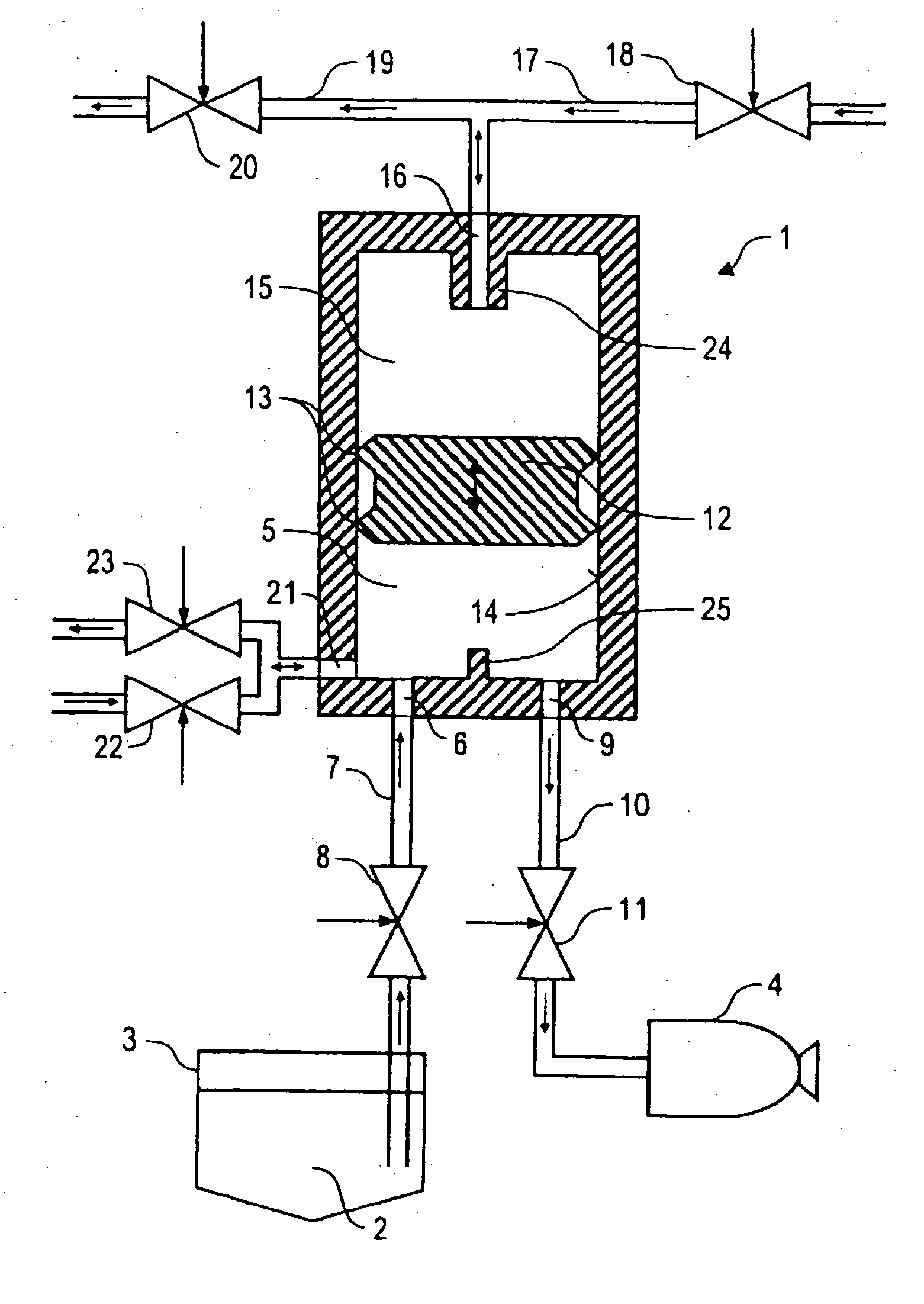
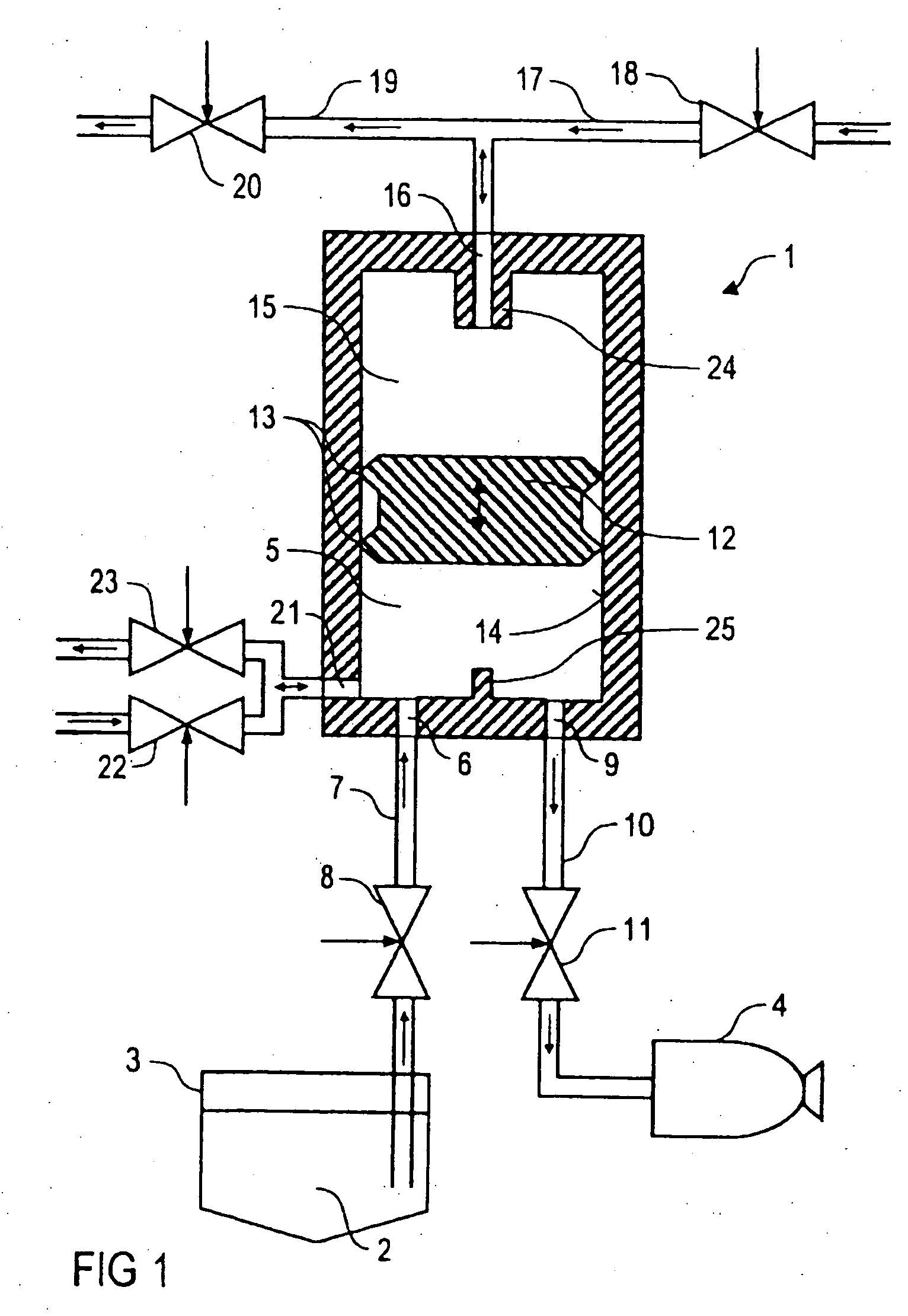
[0027] The schematic representation in FIG. 1 shows a powder conveying pump 1 that can be used in a powder coating installation to convey powder 2 serving as a coating means from a powder hopper 3 to a rotary atomizer 4 serving as the application device.

[0028] The powder hopper 3 and the rotary atomizer 4 can be of conventional construction so that in what follows a detailed description of the powder hopper 3 and the rotary atomizer 4 can be dispensed with and in this regard reference is made to the relevant technical literature.

[0029] In addition, another application device can be used in place of the rotary atomizer 4, for example, a powder spray gun. Additional parts and components, which are not shown here in the interest of simplicity, can be positioned between the powder hopper 3 and the powder conveying pump 1 and between the powder conveying pump 1 and the rotary atomizer 4.

[0030] The powder conveying pump has a working chamber 5 with a variable working chamber volume. A ...


PUM

PropertyMeasurementUnit
pressureaaaaaaaaaa
volumeaaaaaaaaaa
pressureaaaaaaaaaa

Abstract

A powder conveying pump, in particular for a powder coating device. The pump comprises a working chamber with a variable working chamber volume, a powder inlet opening into the working chamber to suck powder into the working chamber, a powder outlet opening out of the working chamber to expel the powder present in the working chamber and a moveable piston that forms one boundary surface of the working chamber and sucks the powder into the working chamber through the powder inlet during an upward movement. The piston is driven directly by pneumatic means.

Description

CROSS-REFERENCE TO RELATED APPLICATIONS [0001] This application claims priority to U.S. Provisional Patent Application Ser. No. 60 / 653,725 filed on Feb. 17, 2005, the entire contents of which is incorporated herein in its entirety.FIELD OF THE INVENTION [0002] The invention relates to a powder conveying pump, in particular for use in a powder coating installation. DESCRIPTION OF THE RELATED ART [0003] A powder conveying pump is known from DE 101 45 448 A1 and from WO 03 / 024613 A1, which pump can be used in a station for coating media to convey the powder serving as the coating means. The known powder conveying pump has a piston driven mechanically through a piston rod, which generates a vacuum during an upward stroke in a working chamber of the powder conveying pump, sucking the powder into the working chamber of the powder conveying pump through a powder inlet. Transfer air is then blown into the working chamber, whereby the powder present in the working chamber is discharged throu...

Claims


Application Information

Patent Timeline
Patent Type & Authority Applications(United States)
IPC IPC(8): A61M15/00A61M11/00
CPCB05B7/1459F04B9/1207F04B9/127F04B15/02F04F1/02
Inventor DURR, THOMASFRITZ, HANS-GEORGHERRE, FRANK
Owner DURR SYST INC
Why Eureka
Try Eureka