High energy photon power source

a high-energy photon and power source technology, applied in the direction of basic electric elements, electrical equipment, semiconductor devices, etc., can solve the problems of affecting the transmission and receipt of data, damage to certain electrical components, and adverse effects on electronic systems of all types, so as to increase the overall amount of electrical energy produced, high reliability and sensitive

Inactive Publication Date: 2006-08-24
HARRIS CORP
View PDF1 Cites 2 Cited by
  • Summary
  • Abstract
  • Description
  • Claims
  • Application Information

AI Technical Summary

Benefits of technology

[0007] This invention is predicated on the concept of using the phenomena described above to create a passive source of electrical energy which exhibits a long life and is inexpensive, highly reliable, and sensitive. It can operate in extreme environmental conditions, requires little or no maintenance and can be integrated in a wide variety of applications and structures. In the presently preferred embodiment, an energy cell is provided comprising at least one metal element having a high atomic number, at least one second metal element with a comparatively low atomic number and a section of dielectric material located between the first and second metal elements. Such “metal elements” may be plates, a wire and sheath or essentially any other configuration in which metal layers are separated by dielectric material.
[0008] In one example, the energy cell may include a plate formed of gold and another plate formed of aluminum separated by a composite layer. In response to dosage of the plates with x-rays, both the gold plate and aluminum plate eject electrons. But because the gold plate has a comparatively higher atomic number, more electrons are ejected from it than the aluminum plate. This creates an electrical potential across the plates such that when a load is connected to them electrical energy, e.g., an induced electromagnetic force (IEMF) charge, flows from the plates to the load. The energy cell of this invention can be scaled in the sense that the physical size of the metal elements can be altered, as desired, and more than one energy cell may be connected together in series or parallel to increase the overall amount of electrical energy produced depending upon the requirement of a particular application.

Problems solved by technology

In the past, the ejection of electrons from the surface of metals as a result of impingement by x-ray photons or other high energy photons such as gamma rays, had adverse effects on electronic systems of all types.
The ejected electrons can damage certain electrical components, interfere with the transmission and receipt of data and cause other problems.

Method used


Image

  • High energy photon power source
  • High energy photon power source
  • High energy photon power source

Examples


Embodiment Construction

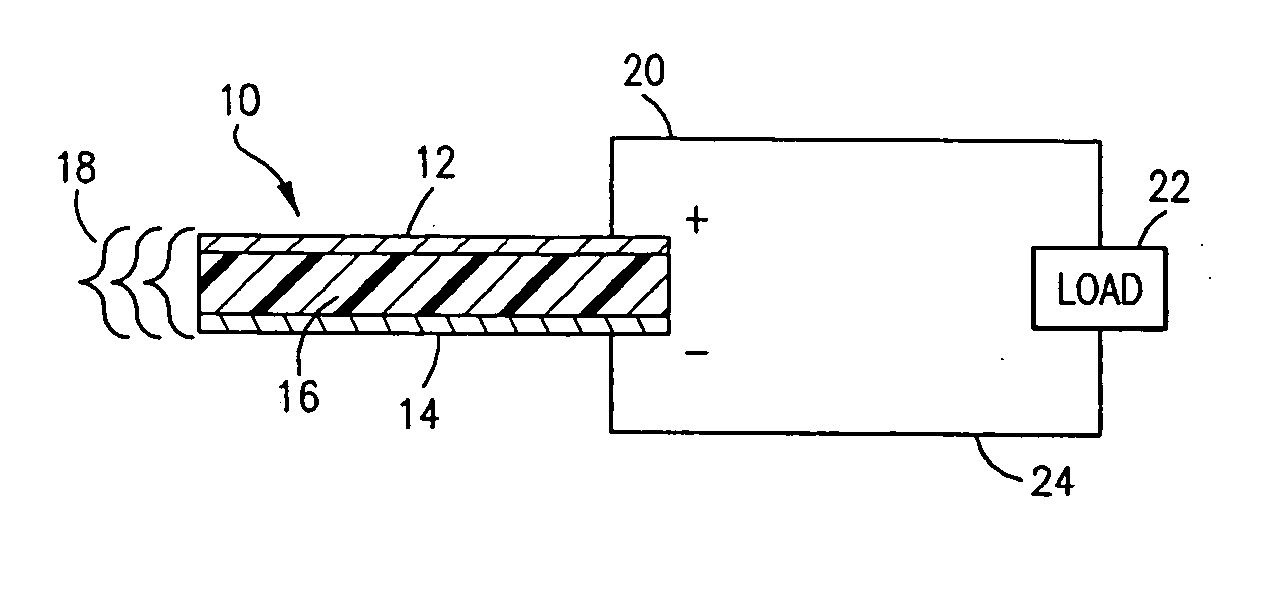
[0015] Referring now to FIG. 1, a schematic view of one embodiment of an energy cell 10 according to this invention is depicted. In this embodiment, the energy cell 10 comprises a first plate 12 and a second plate 14 separated by a layer 16 of dielectric material such as a composite material. The plate 12 is formed of a material having a relatively high atomic number, such as gold, whereas the plate 14 is formed of a material having a comparatively low atomic number such as aluminum. The energy cell 10 is subjected to a dose of high energy photons, such as x-rays or gamma rays, as schematically shown by the brackets 18 in FIG. 1.

[0016] As noted above, all metals eject electrons when impinged by photons of sufficient energy. Materials with higher atomic numbers eject a larger quantity of electrons than those with lower atomic numbers, assuming they are exposed to the same dosage of high energy photons, and therefore a potential difference is produced across the plates 12, 14 which i...


PUM


Abstract

An energy cell, employed as a passive energy source, takes advantage of the differing electrical properties of metals to produce an induced electromagnetic force charge when exposed to dosages of high energy photons such as x-ray or gamma rays.

Description

FIELD OF THE INVENTION [0001] This invention is directed to devices operative in response to impingement by high energy photons, and, more particularly, to a passive energy source which exploits the electrical characteristics of metals having different atomic numbers when exposed to a dosage of high energy photons such as x-rays or gamma rays. BACKGROUND OF THE INVENTION [0002] One of the challenges for many electronics programs is how to reduce the size and weight of electronics components. In larger systems, such as aircraft and spacecraft, every savings in size and weight increases payload and mission capabilities. It is equally important in miniature systems, such as certain types of medical devices, where each reduction can open a range of applications previously inaccessible at larger scales. [0003] One of the key constraints in any electronics system is the demand for some form of local energy to provide power for the system components. Typical solutions include one or more f...

Claims


Application Information

Patent Timeline
Patent Type & Authority Applications(United States)
IPC IPC(8): H01L31/00
CPCH01L31/04H01L31/085Y02E10/50
Inventor ABARE, WAYNE E.WILLIFORD, ROBERT J.HERNANDEZ, ARECIO A.
Owner HARRIS CORP
Why Eureka
Try Eureka