
Apparatus and method for optical wavefront analysis using active light modulation

a technology of active light modulation and optical wavefront, applied in the field of wavefront distortion analysis, can solve the problems of loss of all useful information, inability to overcome problems, density will correspondingly decrease, etc., and achieve faster and more precise wavefront profiling/analysis, the effect of dramatic increase in dynamic range and sensitivity

Inactive Publication Date: 2006-08-24
ALTMAN ZINO +1
View PDF17 Cites 7 Cited by
  • Summary
  • Abstract
  • Description
  • Claims
  • Application Information

AI Technical Summary

Benefits of technology

[0008] The present invention replaces the fixed lenslet array of a conventional SHS with one or more computer-controlled reflective or refractive active light modulation devices (“ALMDs”) that dissect the wavefront formed by passage through or scattering from an object of interest. By so doing, dynamic range and sensitivity may be dramatically increased over conventional devices and methods, thereby allowing faster and more precise wavefront profiling / analysis.

Problems solved by technology

First, if the variance in wavefront slope across a lenslet in a fixed array increases above a certain value, individual wavefronts from different micro-lenses will overlap in the back focal plane, leading to a loss of all useful information.
For a fixed lenslet array this problem cannot be overcome by expanding the wavefront, since the sampling density will be correspondingly decreased.
The potential for overlap is one of the most commonly known shortfalls of SHS technology.
Second, in a conventional SHS, the size of the micro-lenses—around 144 μm in diameter, on average—places an upper limit on the spatial sampling frequency of the SHS.
(The limited fill factor and optical losses of a conventional fixed lenslet array imposing a further limit on the accuracy of the wavefront sensing.)
Third, the micro lenses that are used in conventional SHSs have fixed focal distances and spacings that allow for a only a limited dynamic range.
As discussed above, any attempt to increase the dynamic range of a fixed lenslet array will inevitably be offset by a loss in its sensitivity.

Method used


Image

  • Apparatus and method for optical wavefront analysis using active light modulation
  • Apparatus and method for optical wavefront analysis using active light modulation
  • Apparatus and method for optical wavefront analysis using active light modulation

Examples


Embodiment Construction

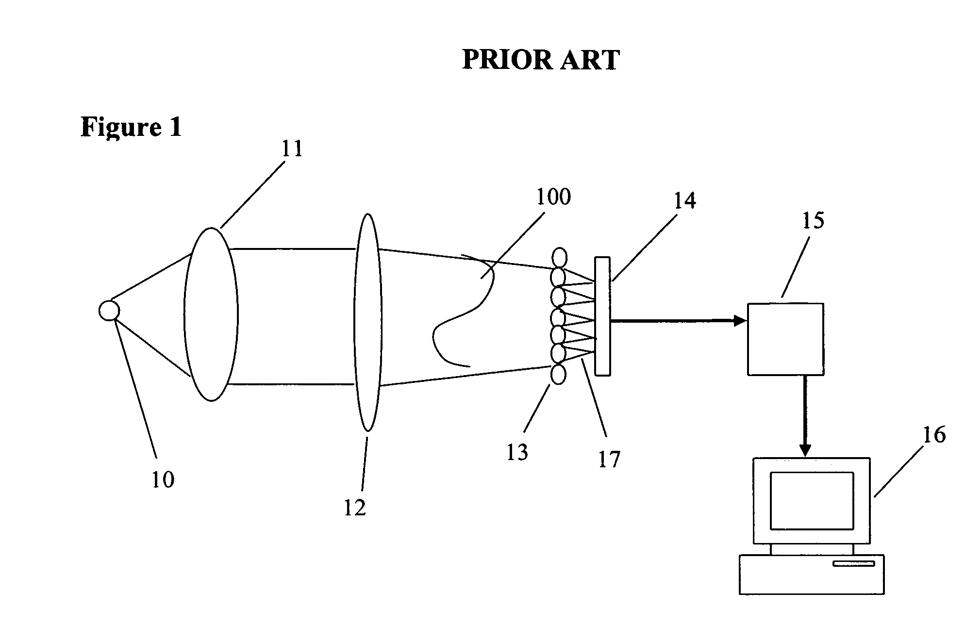
[0021]FIG. 1 is a schematic of a conventional SHS. A wavefront 100 created by light source 10 and a condenser lens or lens system 11 is distorted by an optical or other element 12 and dissected by a lenslet array 13 into plurality of sub fronts 17 that are focused onto a photo sensor 14. The signal from photo sensor14 is processed by the processor 15 and sent to personal computer 16 for final data analysis and wavefront reconstruction.

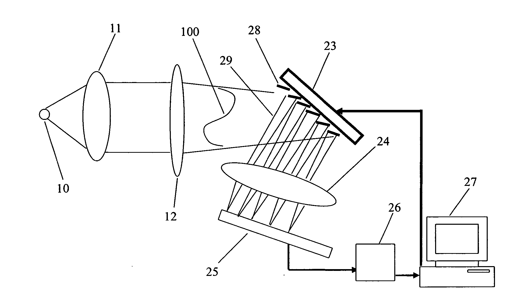
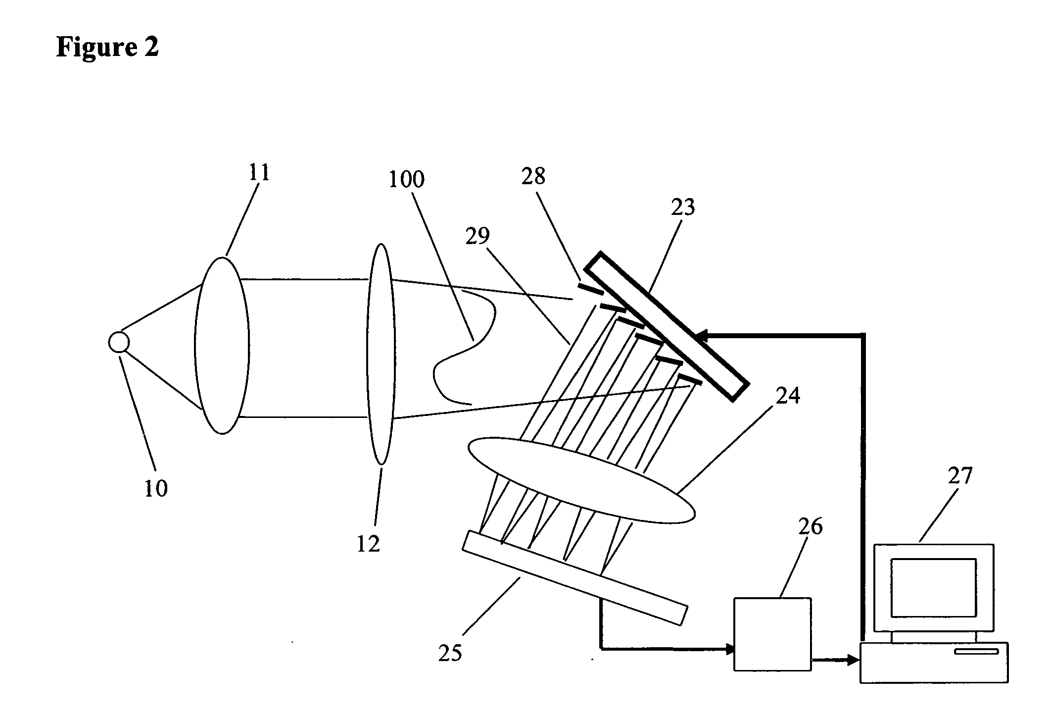
[0022] An embodiment of the invention is shown in the schematic of FIG. 2. A single ALMD 23 having reflective elements 28 is used in place of the conventional lenslet array of FIG. 1. (Such reflective ALMDs are commercially available from Texas Instruments (DMD), Silicon Light Machines, Corning, Agere Systems, Hitachi, Mitsubishi, Daewoo.) A wavefront or wavefront portion 100 created by light source 10 and a condenser lens or lens system 11 is distorted by an optical or other element 12 and then reflected by individual reflective elements 28 of an ALM...


PUM


Abstract

Apparatus and method for measuring wavefront slope and irradiance of direct and / or reflected light beams at a plurality of points to enable calculation of optical wave front distortions. A plurality of sub-beams or groups of sub-beams is created and controlled using at least one electronically-controlled Active Light Modulation Device (“ALMD”).

Description

FIELD OF THE INVENTION [0001] The present invention relates to wavefront distortion analysis and constitutes an improvement of known Schack-Hartmann analyzer / sensors that are used to analyze wavefront distortion / variation. BACKGROUND OF THE INVENTION [0002] The Shack-Hartmann sensor (or “SHS”) was first developed by Ben Platt and Roland Shack in 1970 as part of a classified U.S. Air Force laser project and has since seen widespread use in the measurement of wavefront aberrations in a variety of optical systems in fields ranging from astronomy to opthalmics. The SHS analyzes a wavefront transmitted by, or scattered from, an object of interest by dissecting the wavefront into a large number of subfronts using an array of microscopic lenses. The object of interest is frequently a component or components of an optical system having selected and pre-defined optical properties. [0003] In the conventional SHS the array comprises micro-lenses or lenslets disposed in the same plane, such tha...

Claims


Application Information

Patent Timeline
Patent Type & Authority Applications(United States)
IPC IPC(8): G01J1/20H01L27/00
CPCG01J9/00
Inventor ALTMAN, ZINOKOPLIN, RICHARD S.
Owner ALTMAN ZINO
Learn More