Light emitting device provided with lens for controlling light distribution characteristic

a technology of light distribution characteristic and light emitting device, which is applied in the direction of discharge tube luminescnet screen, discharge tube/lamp details, electric discharge lamps, etc., can solve the problems of color unevenness, color tone difference, and difficulty in controlling the quantity of fluorescent material dispersed, and achieve good light distribution characteristic, low profile, and easy manufacturing

Active Publication Date: 2006-08-24
NICHIA CORP
View PDF20 Cites 161 Cited by
  • Summary
  • Abstract
  • Description
  • Claims
  • Application Information

AI Technical Summary

Benefits of technology

[0017] An object of the present invention is to provide a light emitting device having a lens formed in a transparent layer that...

Problems solved by technology

However, since it is difficult to control the quantity of the fluorescent material dispersed in the resin which fills in the light emitting device, a problem of difference in color tone due to different amounts of fluorescent material among individual devices arises.
In the light emitting device that combines the light emitting diode and the fluorescent material, color unevenness often becomes a problem that the emitted light show different colors depending on the direction of view.
However, in case a lens is formed on the light emitting surface of the surface mounted type...

Method used


Image

  • Light emitting device provided with lens for controlling light distribution characteristic
  • Light emitting device provided with lens for controlling light distribution characteristic
  • Light emitting device provided with lens for controlling light distribution characteristic

Examples


first embodiment

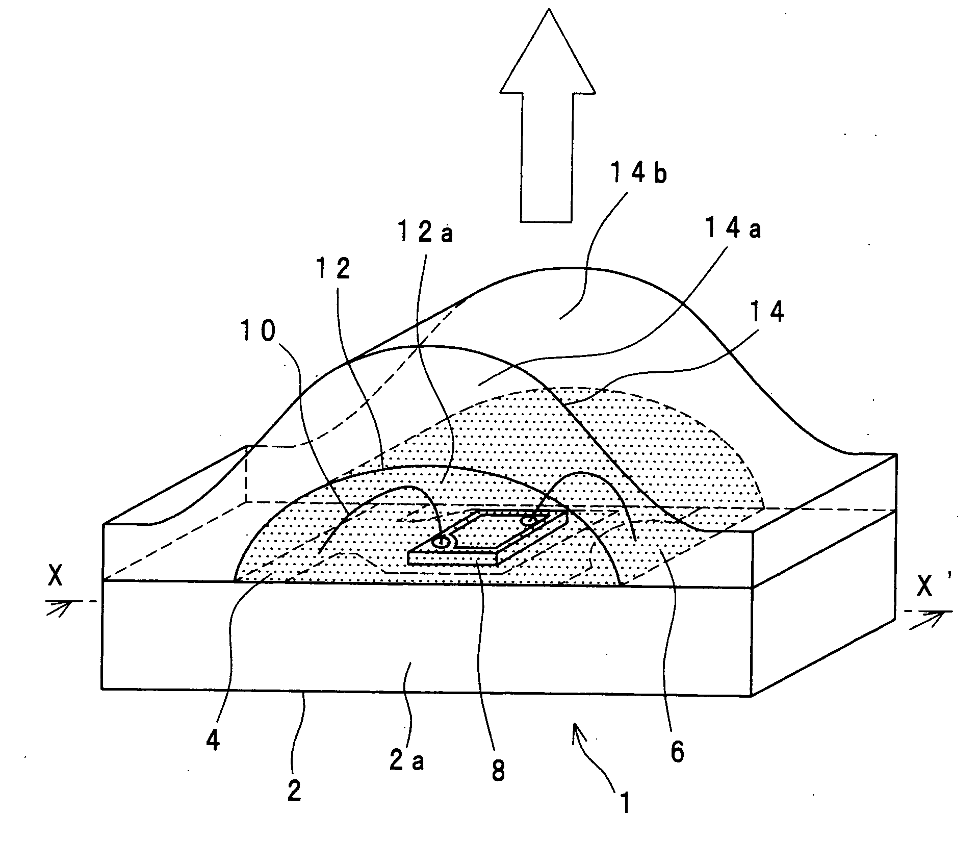
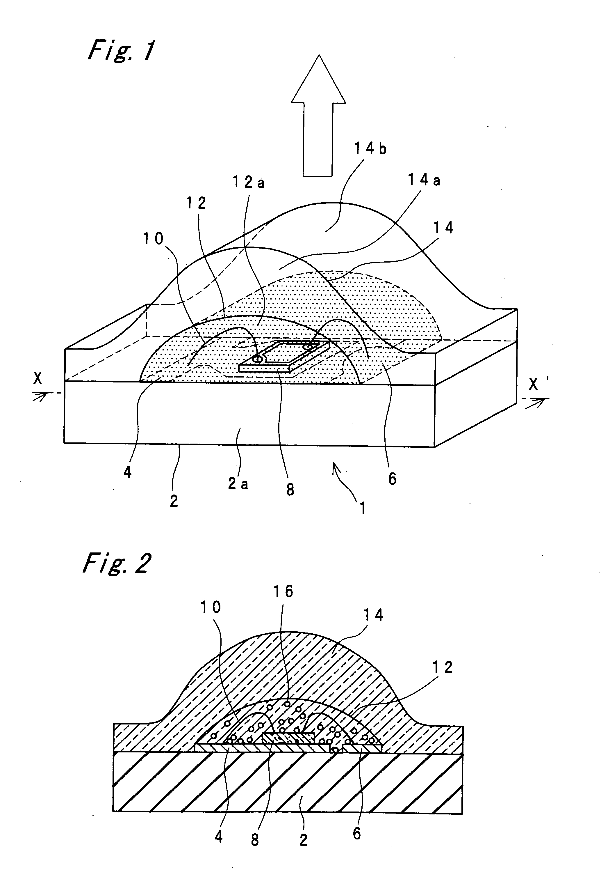
[0066] AS shown in FIG. 1, the light emitting device according to this embodiment comprises a substrate 2, a positive electrode 6 and a negative electrode 4 formed on the substrate 2, a light emitting diode 8 connected to the positive electrode 6 and negative electrode 4, transparent resin layers (12 and 14) that cover the light emitting diode 8, and a fluorescent material 16 that is dispersed in the transparent resin layers 12 and 14, wherein the fluorescent material 16 that is dispersed in the transparent resin layers 12 and 14 is excited with the light emitted by the light emitting diode to emit light of a color different from that of the light emitted by the light emitting diode 8. The transparent resin layers 12 and 14 that cover the light emitting diode 8 consist of the first transparent resin layer 12 that includes the fluorescent material 16 and the second transparent resin layer 14 formed on the first transparent resin layer 12. The second transparent resin layer 14 is proc...

second embodiment

[0114] In this embodiment, an example of forming the first transparent resin layer 12 by printing process will be described. The process is similar to that of the first embodiment with other respects.

[0115] First, as shown in FIG. 8A, the first transparent resin layer 12 is formed by printing over the entire surface of the package assembly 5. The first transparent resin layer 12 is formed over the entire surface of the insulating substrate 2, and is flat on the top surface. Thickness of the first transparent resin layer 12 is kept large enough to be higher than the wire 10, so that the wire 10 does not bend or break when the first transparent resin layer 12 is printed. Then the first transparent resin layer 12 is heated to harden.

[0116] Then the second transparent resin layer 14 having the lens formed therein is formed by a method similar to that of the first embodiment on the first transparent resin layer 12 that has been formed over the entire surface of the insulating substrate...

third embodiment

[0118] In the third embodiment, a method for suppressing the fluorescent material 16 from spreading while forming the first transparent resin layer by the printing method will be described.

[0119] First, as shown in FIG. 9A, before the first transparent resin layer 12 is formed by printing, a mask 30 that limits the range of printing the first transparent resin layer 12 is formed on the insulating substrate 30. The mask 30 is formed from, for example, a resist. The mask 30 may be formed in parallel stripes that interpose the array of the light emitting diode 8 from the right and left, so as to limit the range of printing the first transparent resin layer 12 within the vicinity of the light emitting diode 8.

[0120] After hardening the first transparent resin layer 12, the mask 30 is removed. Then the second transparent resin layer 14 is formed by a method similar to that of the first embodiment. After hardening the second transparent resin layer 14, the light emitting device 1 is obt...


PUM


Abstract

The light emitting device comprises a substrate (2), a positive electrode (6) and a negative electrode (4) formed on the substrate (2), a light emitting diode (8) connected to the positive electrode (6) and the negative electrode (4), the transparent resin (12 and 14) that covers the light emitting diode (8), a fluorescent material (16) that absorbs at least part of light emitted by the light emitting diode (8) and converts it to light of longer wavelength, and the lens that changes the direction of light emission from the light emitting diode (8) and/or the fluorescent material (16). The resin (12 and 14) includes the fluorescent material (16) and is formed so as to constitute the lens of substantially semi-cylindrical shape, and the fluorescent material (16) included in the resin (12 and 14) is distributed with a higher concentration in a region near the surface of the light emitting diode (8) than in a region near the surface of the portion that constitutes the lens.

Description

BACKGROUND OF THE INVENTION [0001] 1. Field of the invention [0002] The present invention relates a light emitting device that is capable of emitting light of various colors by combining a light emitting diode and fluorescent materials, and particularly to a light emitting device that has a lens for controlling the light distribution characteristic. [0003] 2. Background Art [0004] In recent years, the development of the blue light emitting diode that utilizes nitride semiconductor has made it possible to manufacture light emitting devices that emit light of various colors by combining the blue light emitting diode and fluorescent materials which absorb at least part of light emitted by the light emitting diode and emit light of different color tones. A light emitting diode that emits white light, in particular, can be made by using a blue light emitting diode as the light emitting diode and a fluorescent material which absorbs part of light emitted by the blue light emitting diode a...

Claims


Application Information

Patent Timeline
IPC IPC(8): H01L33/00H01L33/50H01L33/54
CPCH01L33/505H01L33/508H01L33/54H01L25/0753H01L33/507H01L33/62H01L2224/45144H01L2224/48091H01L2924/00014H01L2924/00
Inventor MIKI, TOMOHIDETAKINE, KENJIYAMASHITA, RYOHEI
Owner NICHIA CORP
Why Eureka
Try Eureka