Charge control method of capacitor in thyristor converter

a capacitor and thyristor technology, applied in the direction of electric variable regulation, dc circuit to reduce harmonics/ripples, instruments, etc., can solve the problems of thyristor being fired at an erroneous, high current initially flowing, and longer charging tim

Inactive Publication Date: 2006-08-24
YASKAWA DENKI KK
View PDF15 Cites 7 Cited by
  • Summary
  • Abstract
  • Description
  • Claims
  • Application Information

AI Technical Summary

Benefits of technology

[0008] The preferred embodiments of the present invention have been developed in view of the above-mentioned and / or other problems in the related art. The preferred embodiments of the present invention can significantly improve upon existing methods and / or apparatuses.

Problems solved by technology

In such converter, however, steep and high current initially flows when an AC power source is turned on in a state in which a condenser is not charged.
However, this causes a longer charging time.
In a conventional thyristor converter, since the steps of detecting the phase detection using the voltage detection as it is and the voltage difference of the AC voltage and the capacitor voltage and charging a capacitor while controlling the firing angle have been employed, there was such problem that the thyristor was fired at an erroneous timing since no constant voltage difference could be obtained due to a failure of accurate power supply phase detection and voltage detection in cases where the detected power supply voltage had distortion.
There also were problems that charging time was dispersed due to the connected power supply impedance and the capacitance of the capacitor and that the charging time increased due to the single phase thyristor firing control.

Method used


Image

  • Charge control method of capacitor in thyristor converter
  • Charge control method of capacitor in thyristor converter
  • Charge control method of capacitor in thyristor converter

Examples


Embodiment Construction

[0024] In the following paragraphs, some embodiments of the invention will be described by way of example and not limitation. It should be understood based on this disclosure that various other modifications can be made by those in the art based on these illustrated embodiments.

[0025] Hereinafter, referable embodiments of the method according to the present invention will be explained with reference to the attached drawings.

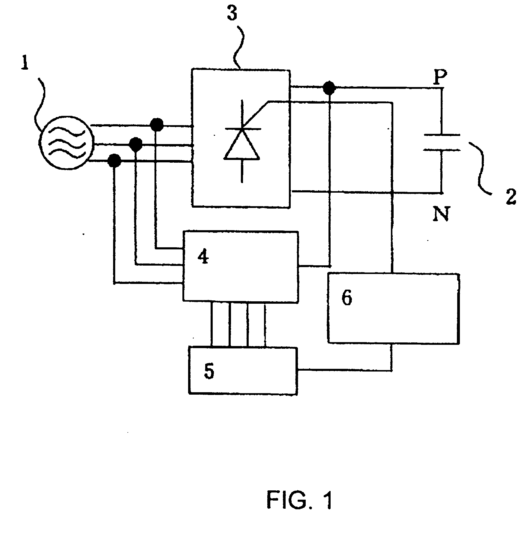
[0026]FIG. 1 shows a block diagram showing the structure of a thyristor converter for executing the method of the present invention. In FIG. 1, the reference numeral “1” denotes an AC power supply, the reference numeral “2” denotes a capacitor, the reference numeral “3” denotes a thyristor module, the reference numeral “4” denotes a voltage detection circuit, and the reference numeral “5” denotes a CPU. The reference letter “P” denotes an output side positive DC bus line of the thyristor module 3, and “N” denotes an output side negative DC bus line of the thyri...


PUM


Abstract

Charging time of a capacitor is shortened while avoiding erroneous firing due to distortion of a power supply voltage and sustaining an inrush current at a constant level. In the charge control method of a capacitor in a thyristor converter comprising a thyristor for rectifying an AC voltage, a CPU delivering an on/off control signal to a thyristor driver for driving the thyristor, a voltage detection sensor for measuring the AC voltage and the capacitor charging voltage, and the capacitor connected with a DC circuit, the AC voltage and the capacitor charging voltage are measured by means of the voltage detection sensor, differential voltage between the firing phase voltage of the thyristor and the capacitor charging voltage is determined, and the thyristor is fired only when the firing phase voltage of the thyristor becomes lower than a specified voltage determined from the differential voltage.

Description

[0001] This application is a continuation-in-part of International Application No. PCT / JP2004 / 10406 filed on Jul. 22, 2004.FIELD OF THE INVENTION [0002] The present invention relates to a charge control method of a capacitor in a thyristor converter for converting an AC voltage into a DC voltage. BACKGROUND OF THE INVENTION [0003] The following description sets forth the inventor's knowledge of related art and problems therein and should not be construed as an admission of knowledge in the prior art. [0004] In a conventional converter, it is required to put a resistor in a power supply line to restrict an inrush current due to a rectification by a diode bridge. In such converter, however, steep and high current initially flows when an AC power source is turned on in a state in which a condenser is not charged. In order to restrain such current, it is required to increase the value of resistance to be inserted in the power supply line. However, this causes a longer charging time. In ...

Claims


Application Information

Patent Timeline
Patent Type & Authority Applications(United States)
IPC IPC(8): H02J7/00H02M7/12
CPCH02M7/125
Inventor TAKAHASHI, HAJIMEHIRAMATSU, KAZUHIKO
Owner YASKAWA DENKI KK
Why Eureka
Try Eureka