Blade-cleaning device and blade member supporting method

a blade and supporting device technology, applied in the direction of optics, electrographic process equipment, instruments, etc., can solve the problems of reducing the yield rate of defective blades for exchange, difficulty in producing a large amount of blades, and leaking of toner collected by the blade in the longitudinal direction, so as to improve the yield rate of defective blades

Inactive Publication Date: 2006-08-24
KK TOSHIBA +1
View PDF0 Cites 13 Cited by
  • Summary
  • Abstract
  • Description
  • Claims
  • Application Information

AI Technical Summary

Benefits of technology

[0009] An object of an embodiment of the present invention, in a blade cleaning device, is to enable use as blades for exchange even if the dimensional tolerance limits of blades are varied, prevent collected toner from leakage, and improve the yield rate of defective blades.
[0010] According to the embodiment of the present invention, there is provided a blade cleaning device comprising a blade support member having a fist side and a second side opposite to the first side; a blade member fixed to the blade support member so as to slide an...

Problems solved by technology

In such a blade cleaning device, toner collected by the blade may leak from both sides of the blade in the longitudinal direction.
However, for a blade for a cleaning device which is mainly made of polyurethane rubber, it is difficult to produce a large amount of blades with high precision of t...

Method used


Image

  • Blade-cleaning device and blade member supporting method
  • Blade-cleaning device and blade member supporting method
  • Blade-cleaning device and blade member supporting method

Examples


Embodiment Construction

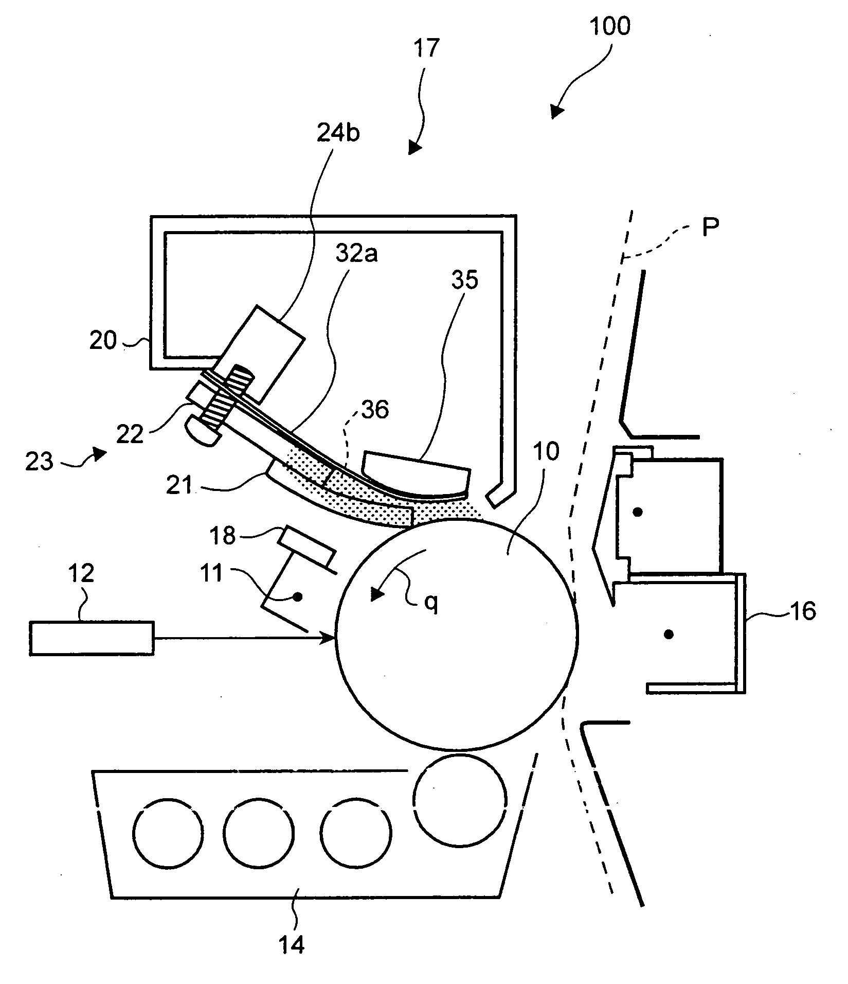
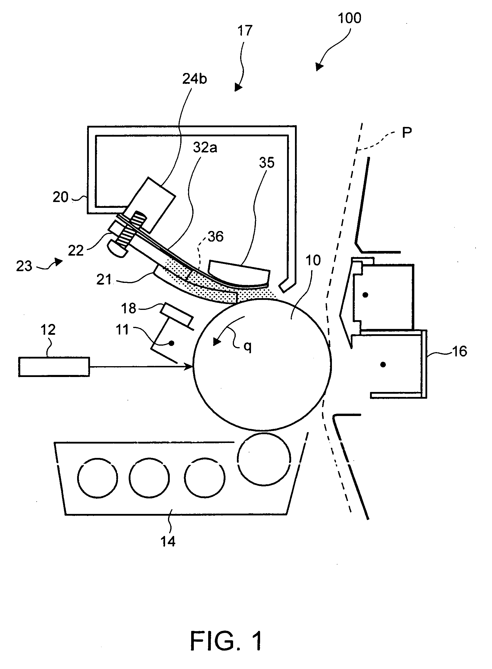
[0021] Hereinafter, the embodiment of the present invention will be explained in detail with reference to the accompanying drawings. FIG. 1 is a schematic block diagram showing image forming unit 100 of an image forming apparatus of an electro-photographic type such as a copier or a printer loading the blade cleaning device of the embodiment of the present invention. Around photosensitive drum 10 which is an image carrying member rotated in the direction of arrow q, in the rotational direction thereof, charger 11, laser exposure unit 12 for forming a latent image on charged photosensitive drum 10 on the basis of image data, developing units 14, transfer-separation charger 16, blade cleaning device 17, and discharging unit 18 are arranged sequentially.

[0022] In image forming unit 100, when the image forming process is started, photosensitive drum 10 is rotated in the direction of arrow q. By doing this, photosensitive drum 10 is uniformly charged by charger 11 and then is irradiated...


PUM


Abstract

A blade cleaning device of the present invention fixes a blade to a blade support member in a state of sliding and moving it in the longitudinal direction and fixes a second side seal member to the blade support member in a state of sliding and moving it in the longitudinal direction on the second side of the blade support member. By doing this, even if the dimensional tolerance limits of the blade are varied, the gap between the blade support member and the blade member can be sealed surely, and the manufacturing accuracy of the blade as a change part is moderated, and the yield rate of defective products is improved.

Description

BACKGROUND OF THE INVENTION [0001] 1. Field of the Invention [0002] The present invention relates to a blade cleaning device for cleaning an image carrying member of an image forming apparatus such as a copier or a printer by a blade and a blade member supporting method. [0003] 2. Description of the Related Art [0004] In an image forming apparatus such as an electro-photographic copier, a printer, or a multifunction peripheral (hereinafter abbreviated to MFP), a blade cleaning device for sliding a blade in contact with a drum-shaped or belt-shaped photoconductor or an intermediate transfer medium after transfer to collect and remove remaining toner may be used. In such a blade cleaning device, toner collected by the blade may leak from both sides of the blade in the longitudinal direction. [0005] Therefore, conventionally, in Japanese Patent Application Publication No. 7-5794, a cleaning device having side seals installed on both sides of a cleaning blade is disclosed. [0006] In the...

Claims


Application Information

Patent Timeline
IPC IPC(8): G03G21/00
CPCG03G21/0029
Inventor YUGE, KEIJI
Owner KK TOSHIBA
Why Eureka
Try Eureka