Method of clock tree distribution generation by determining allowed placement regions for clocked elements

a technology of clocked elements and placement regions, applied in the direction of generating/distributing signals, instruments, program control, etc., can solve the problems of reducing affecting the efficiency affecting the timing of clock tree leaf elements, so as to achieve the effect of minimizing the cost function

Inactive Publication Date: 2006-08-24
GLOBALFOUNDRIES INC
View PDF6 Cites 54 Cited by
  • Summary
  • Abstract
  • Description
  • Claims
  • Application Information

AI Technical Summary

Benefits of technology

[0020] c) placing each clock tree leaf element at a location within i

Problems solved by technology

Movement of clock tree leaf elements may alter the timing of a circuit due to changes in wire length and, hence, changes in wire delay and capacitive load.
These changes can cause violations of timing requirements to occur by making the slacks exceed a specified limit.
Movement of clocked elements may also cause the number of circuits placed or the number of wires routed in a local region to exceed the capacity of that region, a condition known as placement or wiring congestion.
Thus, the potential congestion caused by the moveme

Method used


Image

  • Method of clock tree distribution generation by determining allowed placement regions for clocked elements
  • Method of clock tree distribution generation by determining allowed placement regions for clocked elements
  • Method of clock tree distribution generation by determining allowed placement regions for clocked elements

Examples


Embodiment Construction

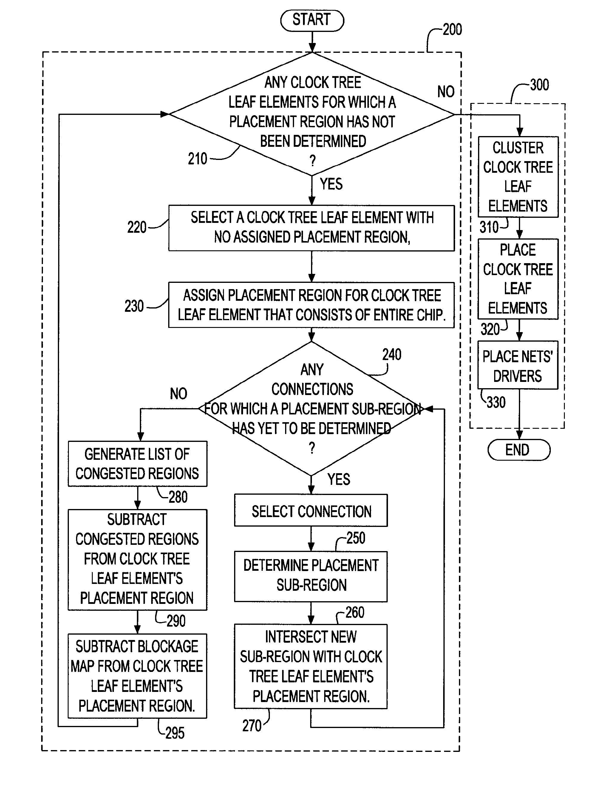
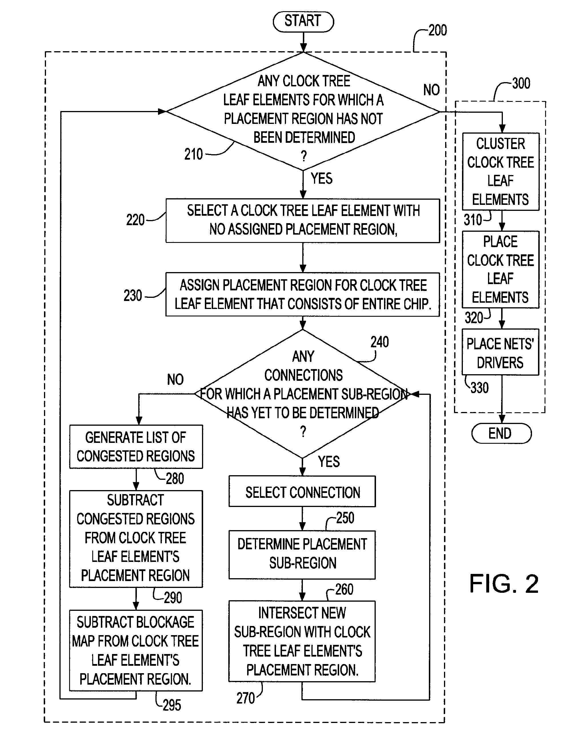
[0036] Referring now to FIG. 2, there is shown a flow chart that illustrates the various method steps of the present invention. The basic algorithm consists of two major steps represented by blocks 200 and 300.

[0037] In step 200, a placement region for each clock tree leaf elements is first determined. This is accomplished by assigning an initial placement region, and repeatedly reducing it by intersecting it with sub-regions formed to account for the various constraints on the placement of the clock tree leaf element. The intersection is determined by finding an overlap of two or more regions. In some circumstances, there may be no location which satisfies all the constraints on the clock tree leaf element. To ensure that at least one legal location is found, the original location of the clock tree leaf element is normally included in all the intersected regions, though it may optionally be excluded if the intersection of all sub-regions is not empty and does not include the origi...


PUM


Abstract

A method, system and program product are described for generating a clock distribution network on an integrated circuit by determining an allowable placement region for each of a set of clock tree leaf elements in the integrated circuit. This allowable placement region is generated by determining and intersecting a set of sub-regions under different constraints, each of which identifies an area in which the clock tree leaf element is placed to satisfy the respective constraint. Constraints for which sub-regions are determined include timing constraints in the form of slacks and congestion constraints. After allowable placement regions have been determined, the clock tree leaf elements are clustered, and each clock tree leaf element is placed at a location within its allowable placement region which minimizes some cost function for that clustering.

Description

BACKGROUND OF THE INVENTION [0001] This invention is related to the field of Design Automation of Very Large Scale Integrated (VLSI) circuit chips, and more particularly, to the determination of allowed placement regions within the chip for clocked elements in a design. [0002] It is known in the art that clock tree generation is intended to create an electrical network to distribute a clock signal to clocked elements for use as a sequencing control for logical operations within a chip. A common type of clock distribution network is a buffered clock tree for which the clock tree generation determines how many clock buffers are needed, how they are to be connected, both to clocked circuit elements at the leaves of the clock tree and to other buffers at upper levels of the clock tree (i.e., levels closer to the root of the tree), and where they are to be placed. Practitioners in the art will fully recognize that a clock buffer in the present context may include any circuit that propaga...

Claims


Application Information

Patent Timeline
IPC IPC(8): G06F17/50
CPCG06F1/10G06F17/5068G06F30/39
Inventor MIGATZ, WILLIAM R.CAMPBELL, PAUL M.HATHAWAY, DAVID J.KUNG, DAVID S.PURI, RUCHIRTREVILLYAN, LOUISE H.
Owner GLOBALFOUNDRIES INC
Why Eureka
Try Eureka