Developing roller and manufacturing method thereof

a technology of developing rollers and manufacturing methods, applied in metal-working equipment, electrographic process equipment, instruments, etc., can solve problems such as image failure risk, and easy disassembly and assembly of toner,

Inactive Publication Date: 2006-08-31
KYOCERA DOCUMENT SOLUTIONS INC
View PDF16 Cites 4 Cited by
  • Summary
  • Abstract
  • Description
  • Claims
  • Application Information

AI Technical Summary

Benefits of technology

[0011] In view of the problem described above, the present invention has been made, and it is an object of the invention to provide a developing roller for developing an electrostatic latent image formed on the surface of an image carrier, which developing roller is capable of preventing image failure such as a ghost image and thin layer disturbance and also providing a favorable image concentration by using therein a developing sleeve having improved toner charge holding property and improved abrasion resistance while giving consideration to environmental problems. It is also an object of the invention to provide a manufacturing method of such a developing roller.

Problems solved by technology

However, repeated use of the developing roller causes gradual abrasion of the surface of the developing sleeve, resulting in failure to uniformly hold the toner on this surface, which leads to a risk of occurrence of image failure.
However, the nickel plating treatment performed on the surface of the developing sleeve included in the developing roller of the developing device described in patent publication 1 provides high abrasion resistance, but raises a concern that the toner charge easily dissipates.
This makes it difficult to hold the toner on the surface of the developing sleeve, which inevitably results in a decrease in the amount of toner moving to the surface of the image carrier, thus leading to a possibility of failure to provide a satisfactory image concentration.
This makes it difficult for the toner to move from the surface of the developing sleeve toward the surface of the image carrier, thus leading to a possibility of a ghost image problem that the image pattern formed in the last development operation adversely influences the next development operation.
Moreover, due to the failure of the toner to move from the surface of the developing sleeve, the toner charge amount increases, thus leading to a risk of occurrence of a phenomenon called thin layer disturbance that the toner becomes massed together on the surface of the developing sleeve.

Method used


Image

  • Developing roller and manufacturing method thereof
  • Developing roller and manufacturing method thereof
  • Developing roller and manufacturing method thereof

Examples


Embodiment Construction

[0030] Hereinafter, a description will be given on the embodiments of the present invention, with reference to FIG. 1 to FIG. 6.

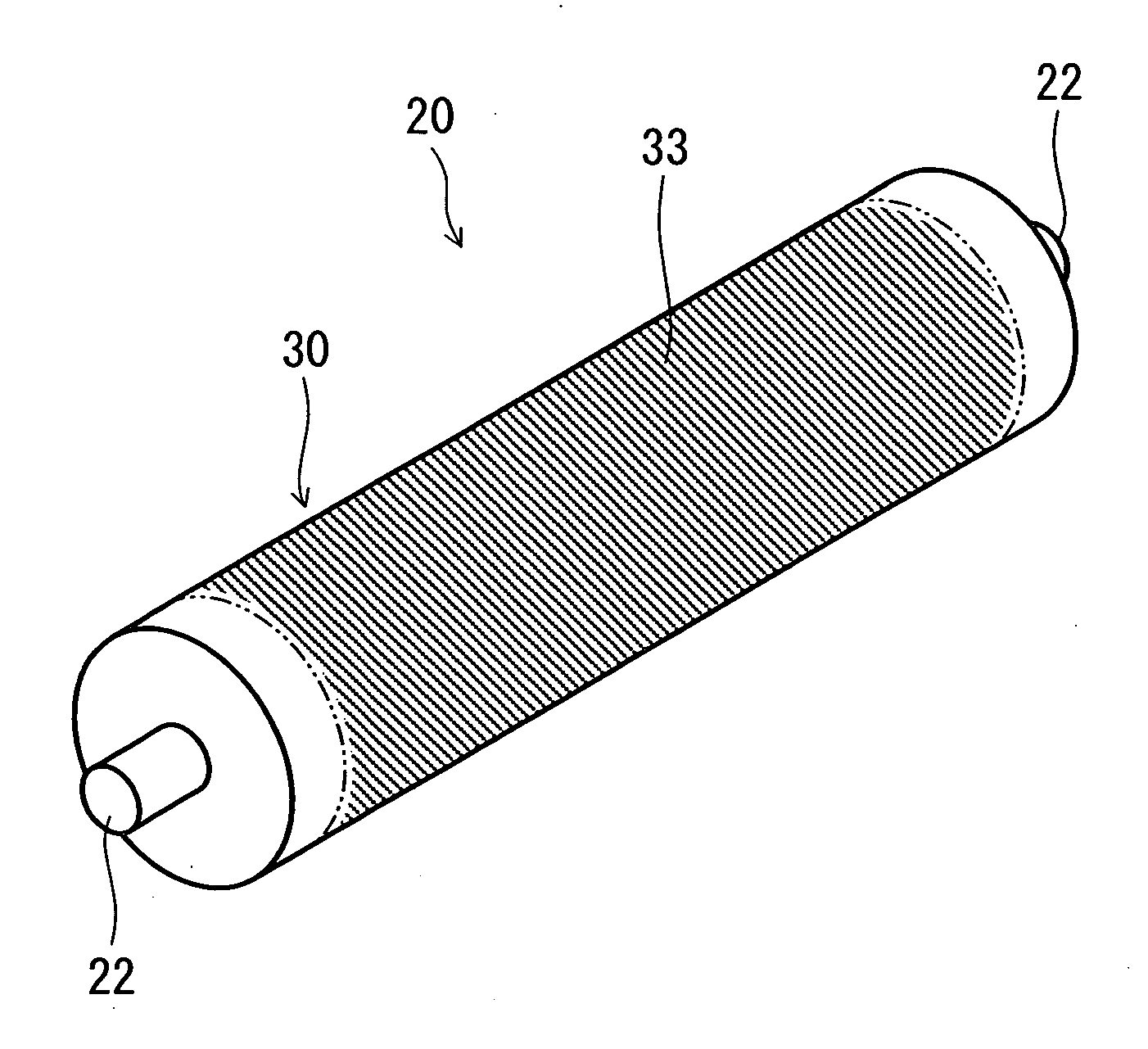
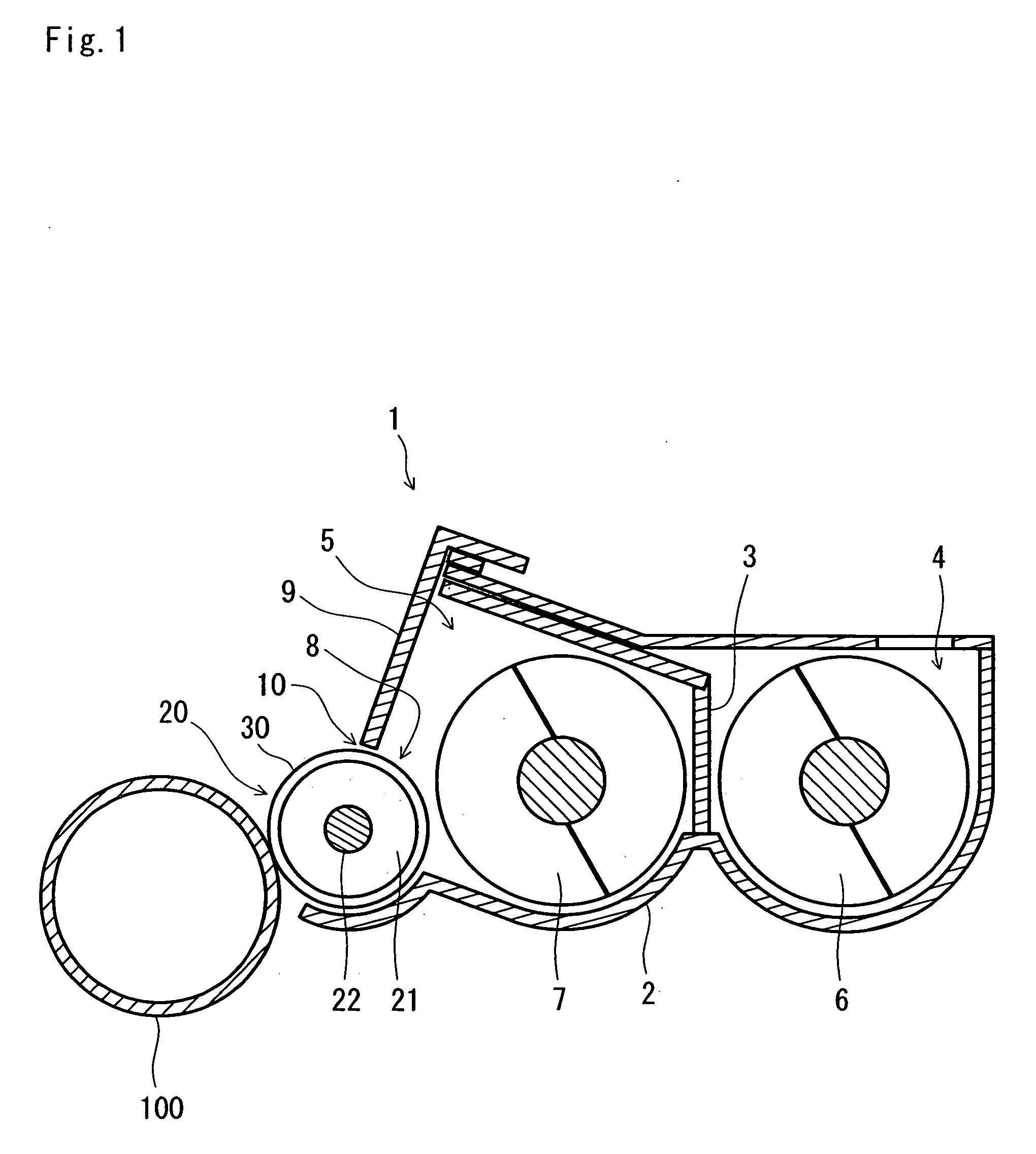
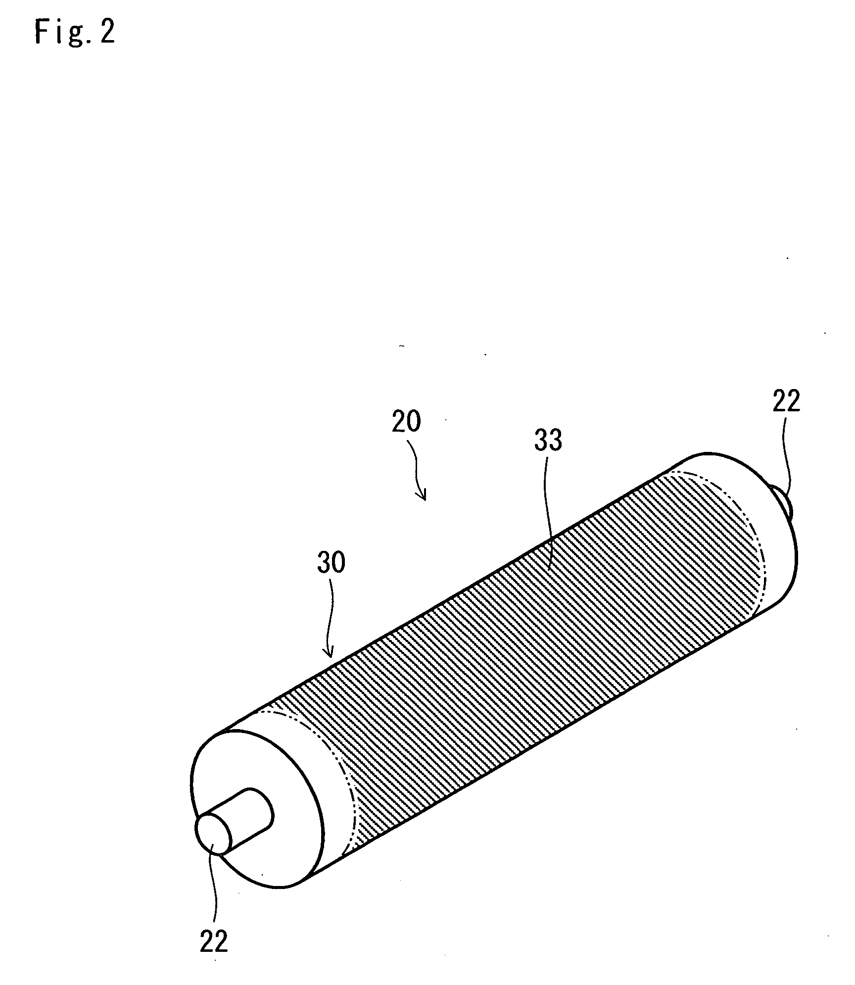
[0031] First, the structure of a developing roller according to the first embodiment of the present invention will be described, with reference to FIG. 1 to FIG. 3. FIG. 1 is a partial vertical sectional elevation of a developing device including the developing roller. FIG. 2 is a schematic perspective view of the developing roller. FIG. 3 is an enlarged partial vertical sectional view of a developing sleeve.

[0032] As shown in FIG. 1, a developing device 1 of an image forming apparatus has a developer container 2. The developer container 2 is so formed as to be elongated in the paper width direction orthogonal to the paper conveyance direction in the image forming apparatus, that is, in the depth direction as viewed on the paper surface of FIG. 1, with its longitudinal direction oriented horizontally. The inside of the developer container 2 is partitioned...


PUM

PropertyMeasurementUnit
thicknessaaaaaaaaaa
thicknessaaaaaaaaaa
electrostatic forceaaaaaaaaaa

Abstract

A developing roller 20 included in a developing device 1 and a photoconductor drum 100 are located adjacently to or in contact with each other. A toner absorbed on the surface of the developing roller 20 moves to the photoconductor drum 100 by an electrostatic force, whereby an electrostatic latent image is formed. The developing roller 20 has on the surface thereof a developing sleeve 30. On the surface of a base 31 of the developing sleeve 30, an electroless nickel plating layer 32 is formed. Further, on the surface of the nickel plating layer 32, a nickel oxide coating 33 is formed. The nickel oxide coating 33 passivates the surface of the developing sleeve 30 to thereby suppress the tendency of the toner charge to dissipate as a result of nickel plating treatment, thus permitting the toner charge holding property to be maintained in a favorable state.

Description

[0001] This application is based on Japanese Patent Application No. 2005-050274 filed on Feb. 25, 2005, the contents of which are hereby incorporated by reference. BACKGROUND OF THE INVENTION [0002] 1. Field of the Invention [0003] The present invention relates to a developing roller applicable to a developing device for use in an electrophotographic image forming apparatus represented by a copier and a printer, and also to a manufacturing method of this developing roller. [0004] 2. Description of the Prior Art [0005] In an electrophotographic image forming apparatus represented by a copier and a printer, after the surface of an image carrier is uniformly charged, an electrostatic latent image of the original image is formed through partial light attenuation of a potential by way of light irradiation, and a visible toner image formed by developing the electrostatic latent image with a toner is transferred onto paper. After the transfer of the toner image onto the paper, the remainin...

Claims


Application Information

Patent Timeline
Patent Type & Authority Applications(United States)
IPC IPC(8): B21D53/00G03G15/10
CPCG03G15/0818Y10T29/4956Y10T29/49563
Inventor HAYASHI, MASAKIUEMURA, SATOSHI
Owner KYOCERA DOCUMENT SOLUTIONS INC
Why Eureka
Try Eureka