Water extraction apparatus and method

a technology of water extraction apparatus and water vapor, which is applied in the direction of chemistry apparatus and processes, separation processes, dispersed particle separation, etc., can solve the problems of large amount of air that must be processed, high energy requirements for condensing water vapor, and large amount of energy consumed for air handling and condensation, etc., to achieve high water absorption capability, high heat of vaporization, and high vaporization temperature

Inactive Publication Date: 2006-08-31
N P JOHNSON FAMILY PARTNERSHIP
View PDF21 Cites 14 Cited by
  • Summary
  • Abstract
  • Description
  • Claims
  • Application Information

AI Technical Summary

Benefits of technology

[0008] For preferred embodiments, pressurized feed air from any source of air, including ambient atmosphere, containing water vapor is supplied to a reactive chamber containing a reagent, preferably sulfuric acid. The water vapor is absorbed from the pressurized feed air by reaction with the reagent and spent air with most of the water removed is discharged to atmosphere. Reagent solution is transmitted to a recovery chamber where concentrated water vapor is extracted from the reagent solution which is heated by recovery heat supplied from an energy source. The concentrated water vapor is extracted in a concentrated vapor zone created by a vacuum pump, which also pressurizes concentrated water vapor for an extraction energy exchanger which discharges extracted water. Heat of cooling and vaporization is extracted from the extraction energy exchanger by a heat exchange device. Concentrated reagent is re-circulated from the recovery chamber to the reactive chamber. The inventor prefers sulfuric acid as the reagent for the reactive chamber, because of its high water absorption capability, high vaporization temperature, high heat of vaporization, and relatively low cost.

Problems solved by technology

The principal challenges that removing water from air with conventional technology presents are the large quantity of air that must be processed and the high energy requirements for condensing the water vapor.
With the relatively low concentration of water vapor in dryer settings where extraction of water from air is more likely to be considered, the low concentration results in the consumption of large amounts of energy for air handling and condensation.

Method used


Image

  • Water extraction apparatus and method
  • Water extraction apparatus and method
  • Water extraction apparatus and method

Examples


Embodiment Construction

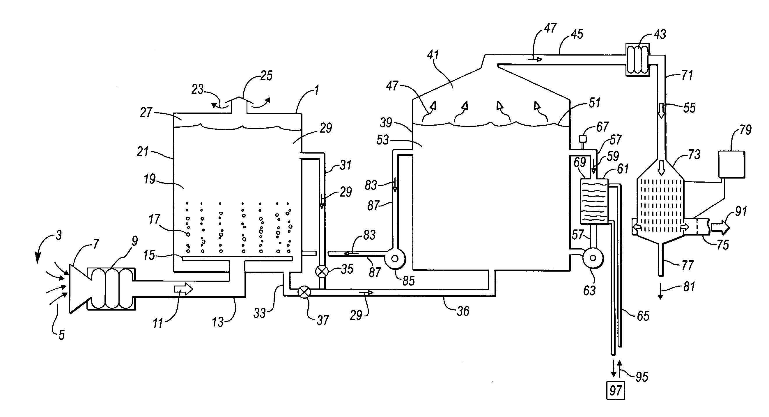
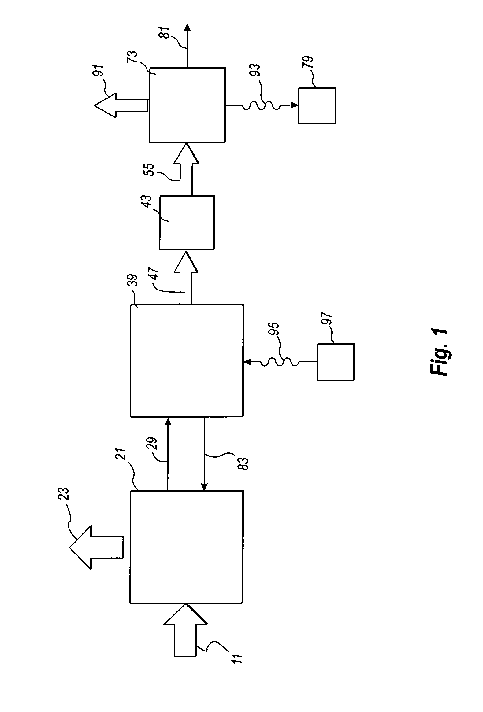
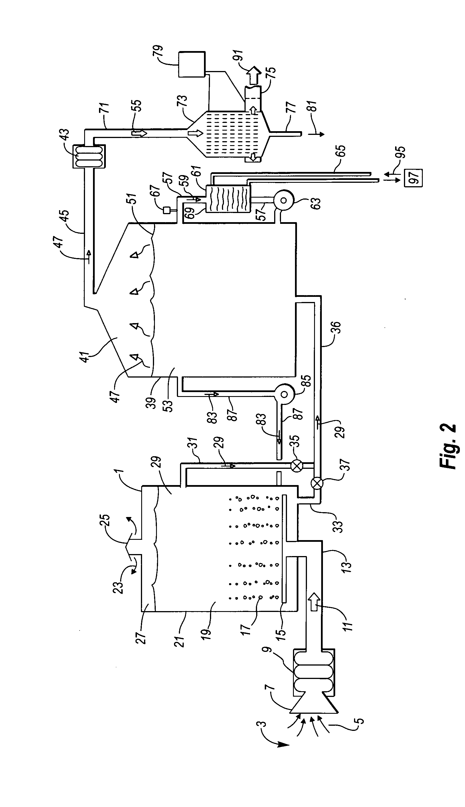
[0021] Referring first to FIG. 1, a block diagram flow chart of a preferred embodiment of the water extraction apparatus 1 of the present invention is shown. Pressurized feed air 11 from any source of air, including ambient atmosphere, containing water vapor is supplied to a reactive chamber 21 containing a reagent with water absorption properties. The inventor prefers sulfuric acid as the reagent. The water vapor is absorbed from the pressurized feed air and spent air 23 with most of the water removed is discharged to atmosphere. Reagent solution 29 is transmitted to a recovery chamber 39 where concentrated water vapor is extracted from the reagent solution which is heated by recovery heat 95 supplied from an energy source 97. The concentrated water vapor is extracted in a concentrated vapor zone created by a vacuum pump 43, which also pressurizes concentrated water vapor for an extraction energy exchanger 73 which discharges extracted water 81. Heat of cooling and vaporization 93 ...


PUM

PropertyMeasurementUnit
temperatureaaaaaaaaaa
pressureaaaaaaaaaa
relative humidityaaaaaaaaaa

Abstract

Apparatus and method for extracting water from air containing water vapor. A feed air assembly supplies air containing water vapor to a diff-user assembly in a reactive tank containing a reagent, preferably sulfuric acid, which absorbs the water vapor from the feed air. The reactive tank vents the dried air. A reagent solution line transmits reagent solution from the reactive tank to a recovery tank. A vacuum pump evaporates concentrated water vapor from the recovery tank and an extraction energy exchanger condenses the concentrated water vapor to liquid water.

Description

FIELD OF THE INVENTION [0001] This invention is in the field of apparatuses and methods for the extraction of water from air and in particular in the field of apparatuses for the extraction of liquid water from air containing water vapor through the use of a chemical reagent. BACKGROUND OF THE INVENTION [0002] In many settings and geographical areas, a scarcity of water, and, in particular a scarcity of potable water, results in the consideration of many alternatives for the development of sources of water. Air containing water vapor is one such source. [0003] Even relatively dry desert air having a relative humidity of ten percent or less is a potential source for a huge quantity of water. The principal challenges that removing water from air with conventional technology presents are the large quantity of air that must be processed and the high energy requirements for condensing the water vapor. The heat of cooling and the heat of vaporization must be extracted from the air in orde...

Claims


Application Information

Patent Timeline
Patent Type & Authority Applications(United States)
IPC IPC(8): B01D53/14
CPCB01D53/263
Inventor JOHNSON, NELDON P.
Owner N P JOHNSON FAMILY PARTNERSHIP
Why Eureka
Try Eureka