Electroplating apparatus

Inactive Publication Date: 2006-08-31
YAMAMOTO MS
View PDF6 Cites 6 Cited by
  • Summary
  • Abstract
  • Description
  • Claims
  • Application Information

AI Technical Summary

Benefits of technology

[0012] With consideration of the above-mentioned problem, it is an object of the present invention to provide an electroplating apparatus which certainly prevents an area other than a surface to be electroplated of an object to be electroplated from being electroplated so as to improve performance and reliability.
[0014] In such a configuration, a pump provided in the vacuum passage can vacuum air in the space surrounded by the first insulated plate, the second insulated plate, the inner seal, and the outer seal so as to make and keep the air pressure in the space negative. Consequently, the whole inner seal can be affixed to the object to be electroplated with even pushing pressure while the whole outer seal can be affixed to the first insulated plate and the second insulated plate with even pushing pressure. Therefore, high sealing performance of the inner seal and the outer seal can be maintained in order to solve the problem that electroplating solution infiltrates into the space so as to cause the area other than the surface to be electroplated of the object to be electroplated to be electroplated. In the present invention, the object to be electroplated may be connected to the negative electrode of a power source so that surface of the object to be electroplated can be electroplated. In addition, the object to be electroplated may be also connected to a positive electrode of a power source so that an anodic film, which is an oxide coating film, can be formed on the surface of the object to be electroplated.
[0018] In such a configuration, the object to be electroplated is fit into the fitting recess formed in the second insulated plate so that a surface of the object to be electroplated facing the first insulated plate and a surface of the second insulated plate facing the first insulated plate can be kept flat. Therefore, thickness of the inner seal attached to the object to be electroplated can be equal to thickness of the outer seal attached to the second insulated plate so as to simplify manufacturing of the inner seal and the outer seal.
[0020] In such a configuration, in vacuuming the air in the space surrounded by the first insulated plate, the second insulated plate, the inner seal, and the outer seal, the temporarily affixing device can temporarily affix the second insulated plate to the first insulated plate in advance before the air in the space is vacuumed by the pump. Accordingly, vacuuming the air in the space in this manner saves an operator from having to affix the second insulated plate to the first insulated plate with his / her hand.

Problems solved by technology

However, it is difficult to equalize tightening pressures of plural screws, so as to cause the tightening pressures of the plural screws to be unbalanced actually.
However, since the larger-sized electroplating apparatus requires more screws, the tightening pressures of the screws become more uneven.

Method used


Image

  • Electroplating apparatus
  • Electroplating apparatus
  • Electroplating apparatus

Examples


Embodiment Construction

[0029] Here will be described embodiments of the present invention in detail, referring to the accompanied drawings as needed.

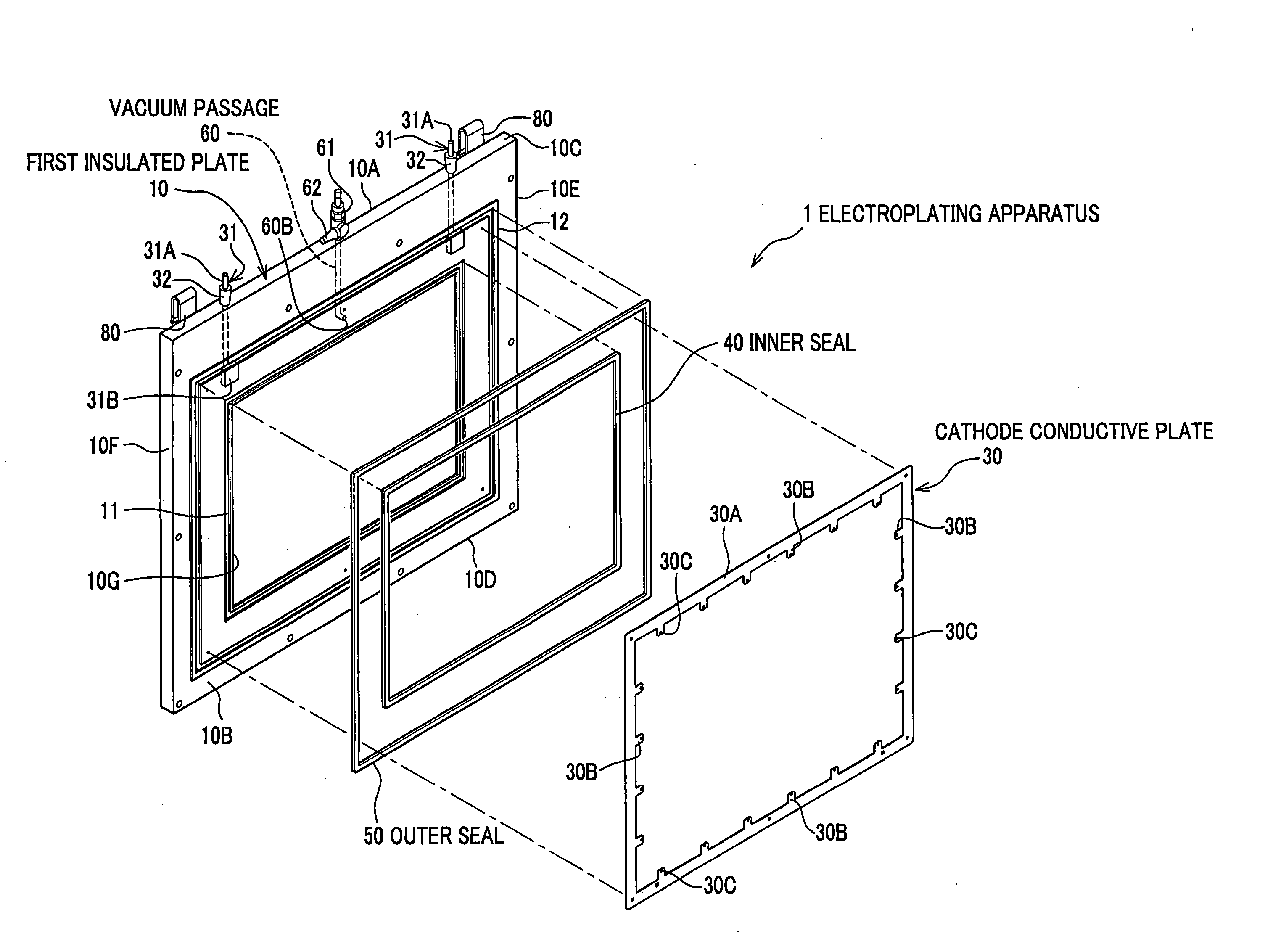
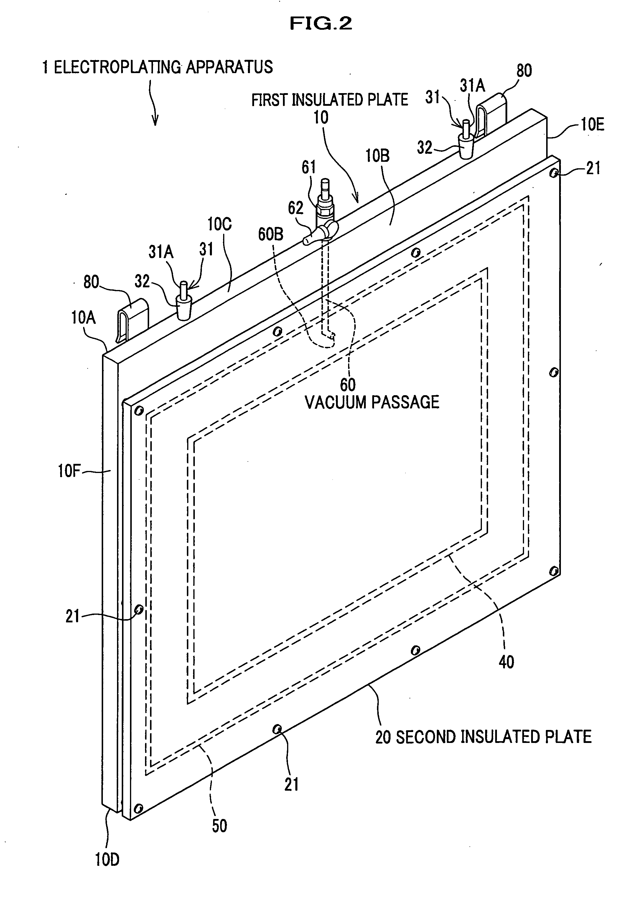
[0030] As shown in FIGS. 1-4, an electroplating apparatus 1 substantially includes a first insulated plate 10, a second insulated plate 20, a cathode conductive plate (a conductor) 30 which conducts electricity, an inner seal 40, an outer seal 50, and a vacuum passage 60.

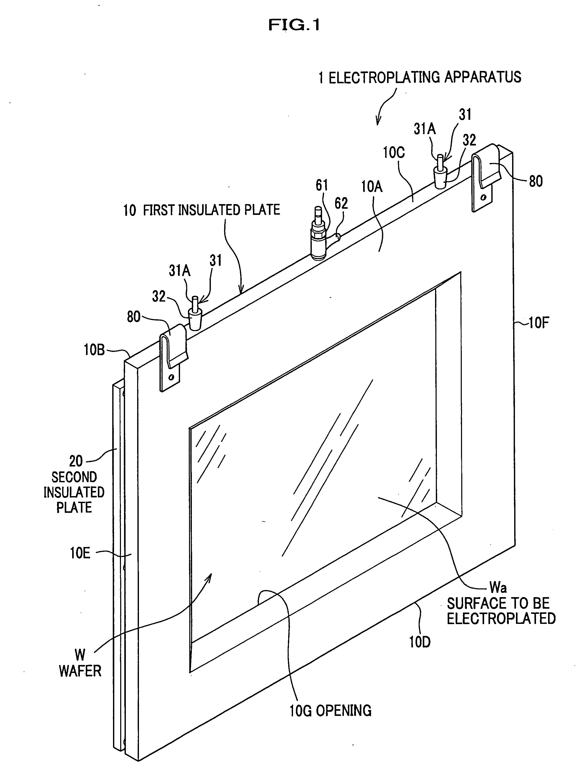
[0031] The first insulated plate 10 is, for example, a flat plate which is made of a insulated material such as an acryl plate and formed in a substantially rectangle shape. As shown in FIGS. 1 and 2, the first insulated plate 10 has a front surface 10A, a back surface 10B, a top surface 10C, a bottom surface 10D, a left side surface 10E, and a right side surface 10F. An opening 10G is formed in a substantially rectangle shape in the first insulated plate 10. Through the opening 10G, a surface Wa to be electroplated of a wafer W, which will be described later, is exposed. Moreover, as shown...


PUM

PropertyMeasurementUnit
Thicknessaaaaaaaaaa
Pressureaaaaaaaaaa

Abstract

An electroplating apparatus including a first insulated plate which has an opening, a second insulated plate which holds an object to be electroplated between the first insulated plate and the second insulated plate in such a way that the object to be electroplated is exposed through the opening, an inner seal which is provided around a periphery of the opening between the first insulated plate and the object to be electroplated, a conductor which is provided between the first insulated plate and the second insulated plate surrounding the object to be electroplated so as to conduct electricity to the object to be electroplated, and an outer seal which is provided between the first insulated plate and the second insulated plate surrounding the conductor, in which a vacuum passage is formed inside the first insulated plate and / or the second insulated plate in order to make and keep air pressure in a space surrounded by the first insulated plate, the second insulated plate, the inner seal, and the outer seal, negative.

Description

CROSS REFERENCE TO RELATED APPLICATIONS [0001] This application claims the foreign priority benefit under Title 35, United States Code, §119(a)-(d) of Japanese Patent Application No. 2005-051215, filed on Feb. 25, 2005 in the Japan Patent Office, the disclosure of which is herein incorporated by reference in its entirety. BACKGROUND OF THE INVENTION [0002] 1. Field of the Invention [0003] The present invention relates to an electroplating apparatus for performing electroplating and anodic oxidation on surfaces of, for example, wafers, glass substrates, and ceramic substrates. [0004] 2. Description of the Related Art [0005] In recent years, electroplating technologies are applied to various kinds of technical fields, including wiring technologies in semi-conductors. In the field of semi-conductors, wiring pitches are required to be reduced to accomplish high integration and performance. For example, in a wiring technology employed in latest years, an interlayer insulated film is form...

Claims


Application Information

Patent Timeline
IPC IPC(8): B23H7/26
CPCC25D17/06H05K2203/1147C25D17/001
Inventor YAMAMOTO, WATARUAKIYAMA, KATSUNORIHARADA, FUMIO
Owner YAMAMOTO MS
Why Eureka
Try Eureka