Combustion head for use with a flame spray apparatus

Active Publication Date: 2006-08-31
TECHN ENG
View PDF48 Cites 4 Cited by
  • Summary
  • Abstract
  • Description
  • Claims
  • Application Information

AI Technical Summary

Benefits of technology

[0021] One advantage of the present invention combustion head and combustion chamber assembly is that the combustion head includes a substantially less amount of material mass as compared to prior art combustion heads. In the prior art combustion heads, the floor of the counterbore was designed to engage the outlet end of the combustion chamber and support the same thereby in part establishing the proper insertion of the combustion chamber into the combustion head. Whereas, in the present invention, the floor of the counterbore is eliminated and the insertion position of the combustion chamber into the combustion head is established and supported by the flange on the outer surface of the combustion head engaging a flat surface on a lower side of the combustion head. The flange eliminates the need for the combustion chamber to abut against the floor of the combustion head, thereby allowing the floor of the counterbore to be eliminated. As set forth above, elimination of the floor of the counterbore results in

Problems solved by technology

One known problem associated with the combustion head of the Browning flame sprayer is that a floor of the counterbore receiving the hot combustion gases from the combustion chamber cracks and erodes after a short period of use, thus, severely limiting the useful life of the combustion head.
Such cracking and erosion occurs due to the development of local hot spots in the counterbore and thermal fatigue of the body of the combustion head adjacent to the counterbore.
One disadvantage associated with the above-identified prior art combustion heads is that the floor of the counterbore, even with the recess therein as disclosed by Webber, includes a substantial mass of material which receives the hot combustion gases from the combustion chamber and is therefore susceptible to cracking due to the expansion and contraction of the combustion head during the heating and cooling thereof.
The mass of the floor of the counterbore also adds to the overall mass of the combustion head thereby contributing to the thermal fatigue of the combustion head over the life thereof due to the cyclic operation of flame spray apparatus under high temperatures.
Additionally, combustion gases contacting the floor of the counterbore cause the floor of the counterbore to erode enlarging the inlets of the combustion gas passages adjacent the counterbore resulting in an uneven flow of gases through the gas passages of the combustion head.
This uneven pressure in the inclined gas conduits causes the coating material entering the nozzle of the apparatus to be pushed towards the side of the throat of the nozzle opposite the inclined gas conduits with the greatest pressure which causes erosion of the throat of the nozzle and shortens the useful life thereof.
Accor

Method used


Image

  • Combustion head for use with a flame spray apparatus
  • Combustion head for use with a flame spray apparatus
  • Combustion head for use with a flame spray apparatus

Examples


Example

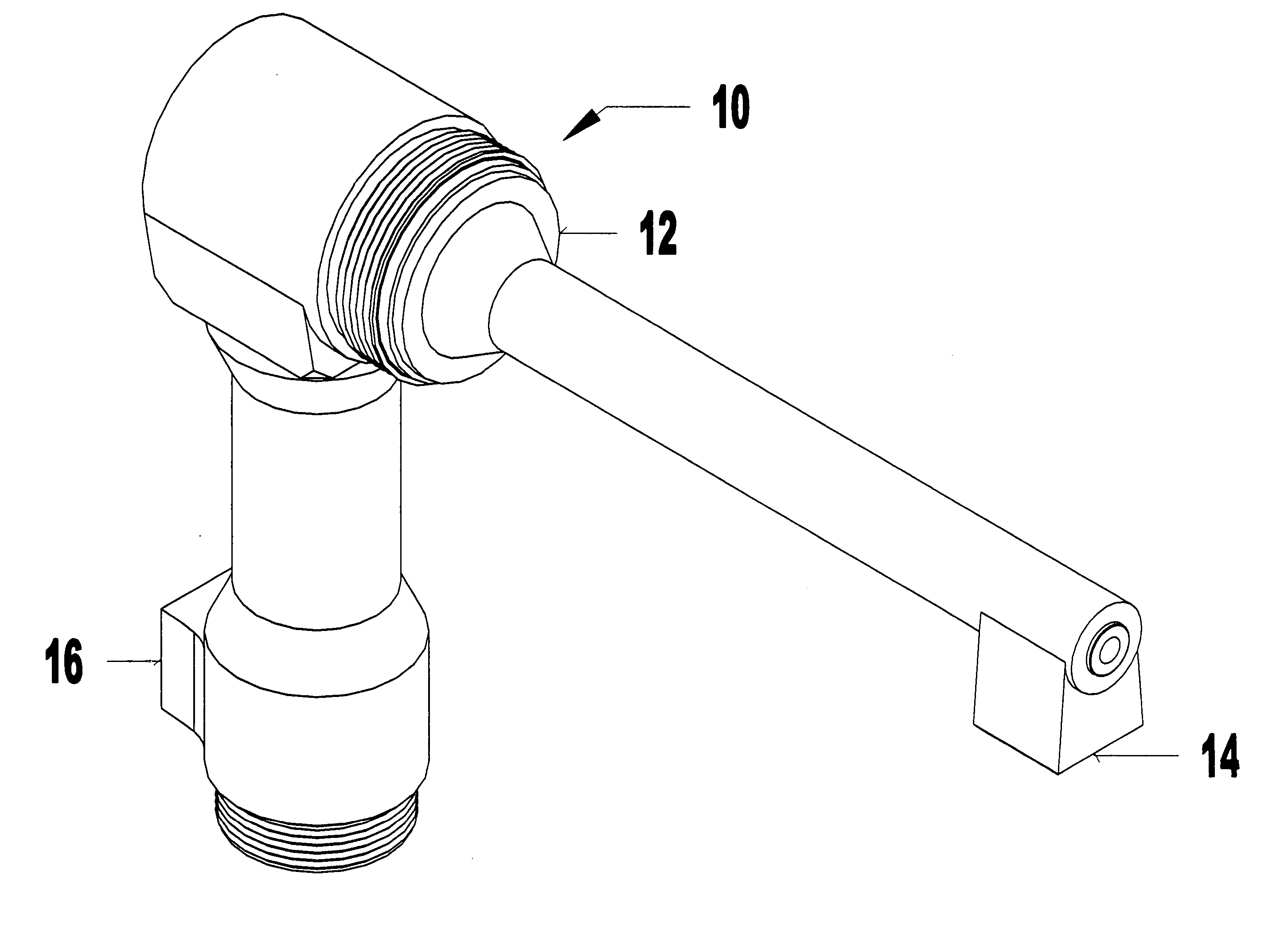
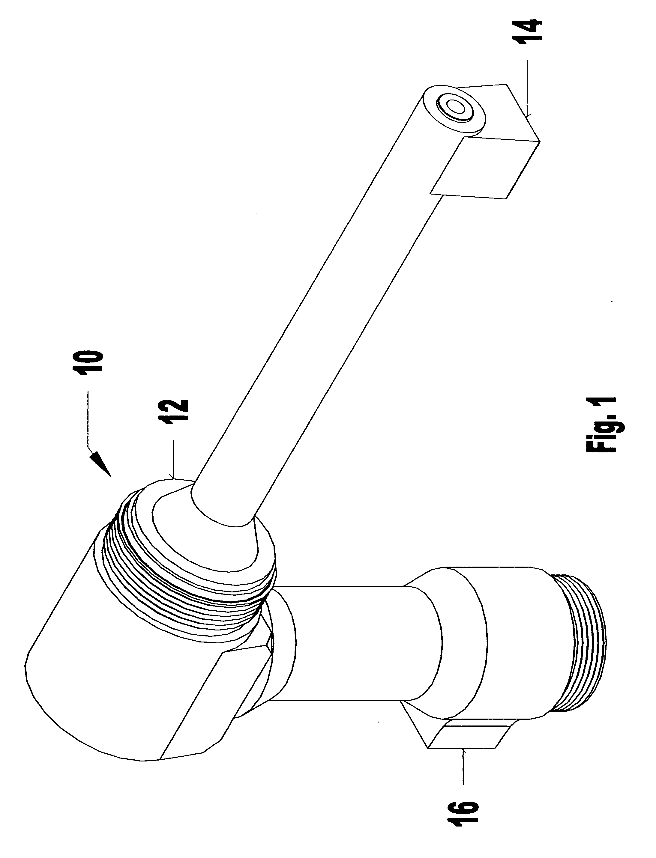
[0037] Referring to the FIG. 1, the present invention combustion head and combustion chamber are designed for use with a typical flame spray apparatus, generally referred to with the reference numeral 10. The flame spray apparatus 10 includes a housing 12. The housing 12 includes a coolant inlet 14 and outlet 16 for cooling the apparatus 10 as well as the combustion head and combustion chamber as shown in FIG. 2 and referenced generally by reference numerals 18 and 20 respectively.

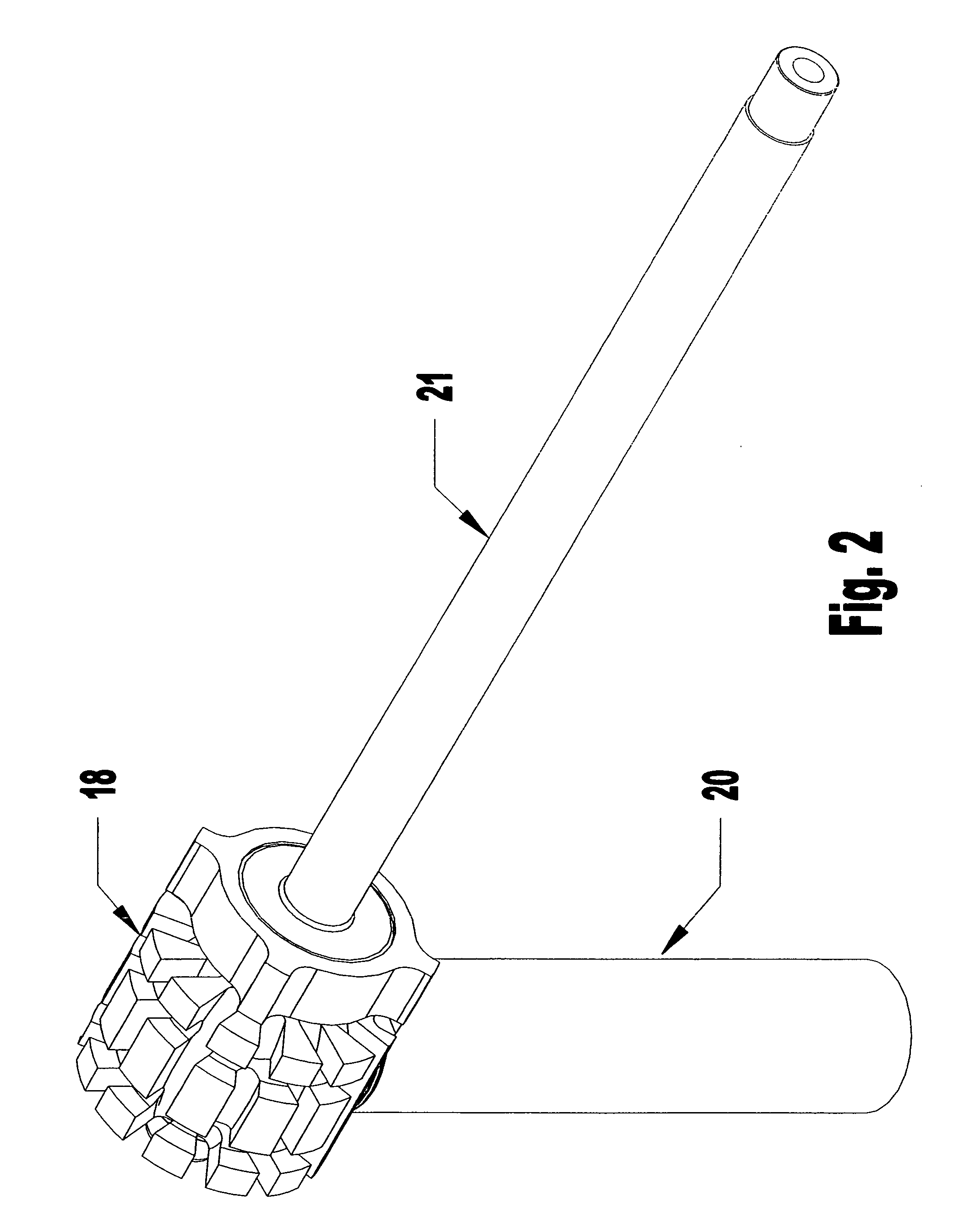
[0038] As shown in FIG. 2, the combustion head 18 and combustion chamber 20 of the present invention are coupled together as set forth in detail following. A nozzle 21 is also coupled to the combustion head forming an assembly for use in a flame spray apparatus 10. FIG. 3 illustrates the combustion head 18 and combustion chamber 20 of the present invention coupled together and mounted in the housing 12 of the flame spray apparatus 10.

[0039] Referring to FIGS. 3-11, the combustion head 18 includes a body ...


PUM

PropertyMeasurementUnit
Thicknessaaaaaaaaaa
Thicknessaaaaaaaaaa
Lengthaaaaaaaaaa

Abstract

The present invention provides an improved combustion head and combustion chamber for use with known flame spray apparatus. The combustion head includes a body portion defining a combustion opening for receiving an outlet end of the combustion chamber and an interior chamber extending from the combustion opening into the body portion. The body portion also defines a material feed conduit extending through the body portion along a longitudinal axis thereof. The body portion being substantially hollow wherein the interior chamber extends from the combustion opening throughout substantially the entire body portion including adjacent the material feed conduit. The body portion defining coolant channels on an outer surface thereof of varying depth such that the wall thickness of the body portion at the coolant channels is substantially uniform. The combustion chamber having a flange formed on an outer surface thereof for limiting insertion of the combustion chamber into the combustion head.

Description

CROSS REFERENCE TO RELATED APPLICATIONS [0001] This application claims priority to U.S. Provisional Patent Application No. 60 / 656,497 filed on Feb. 25, 2005 and titled “Combustion Head For Use With A Flame Spray Apparatus”. The disclosure of the Provisional Application is incorporated in its entirety herein by reference.FIELD OF THE INVENTION [0002] The present invention generally relates to flame spray apparatus for spraying molten or heat softened material onto a workpiece at high velocities by means of hot combustion gases. In particular, the present invention is directed to an improved combustion head and combustion chamber for use with a flame spray apparatus which together work to deliver hot combustion gases and heated coating material to the inlet of a spray nozzle of the apparatus. BACKGROUND OF THE INVENTION [0003] In general, flame spray apparatus operated by hot combustion gases for coating a workpiece with metal are well known in the art. For example, U.S. Pat. No. 4,41...

Claims


Application Information

Patent Timeline
IPC IPC(8): B05B1/24B05B15/00
CPCB05B7/168B05B7/20C23C4/124C23C4/129
Inventor NOUJAIM, MAJED
Owner TECHN ENG
Why Eureka
Try Eureka