
Analysis device for a liquid sample

Inactive Publication Date: 2018-02-15
CONSEJO SUPERIOR DE INVESTIGACIONES CIENTIFICAS (CSIC) +2
View PDF6 Cites 4 Cited by
  • Summary
  • Abstract
  • Description
  • Claims
  • Application Information

AI Technical Summary

Benefits of technology

The proposed analysis device has several advantages: it requires less liquid sample, has a simplified design, requires less material, and is cost-effective. The device allows for easy flow of fluids using capillary action and does not require pumps. It can be made from readily available and biodegradable materials such as paper. The device also has the advantage of using carbon electrodes and conductive tracks, which makes it more biodegradable. The pH of the medium can be adjusted for optimal performance and stability of the enzymes or bacteria used in the electrodes. In summary, the analysis device is a simplified and cost-effective device with improved biodegradability.

Problems solved by technology

Moreover, conventional batteries consume solid reactants, and once depleted, must be discarded or recharged with electricity.
This flow of reactant(s) is normally achieved by using, for example, external pumps, which may result in a complex and expensive configuration of the fuel cell.
This configuration has the disadvantage of requiring means, e.g. an external pump, to provide the liquid reagent through the inlet for the fuel cell to operate.
Thus, in this case, also the obtained configuration is complex and expensive.
Also, using a first fuel cell to cause a flow of a reagent of a second fuel cell would result in a complex system.
However, none of the quoted prior art discloses an analysis device including a single microfluidic analysis channel providing the functionalities of both analysis and detection.

Method used


Image

  • Analysis device for a liquid sample
  • Analysis device for a liquid sample
  • Analysis device for a liquid sample

Examples


Embodiment Construction

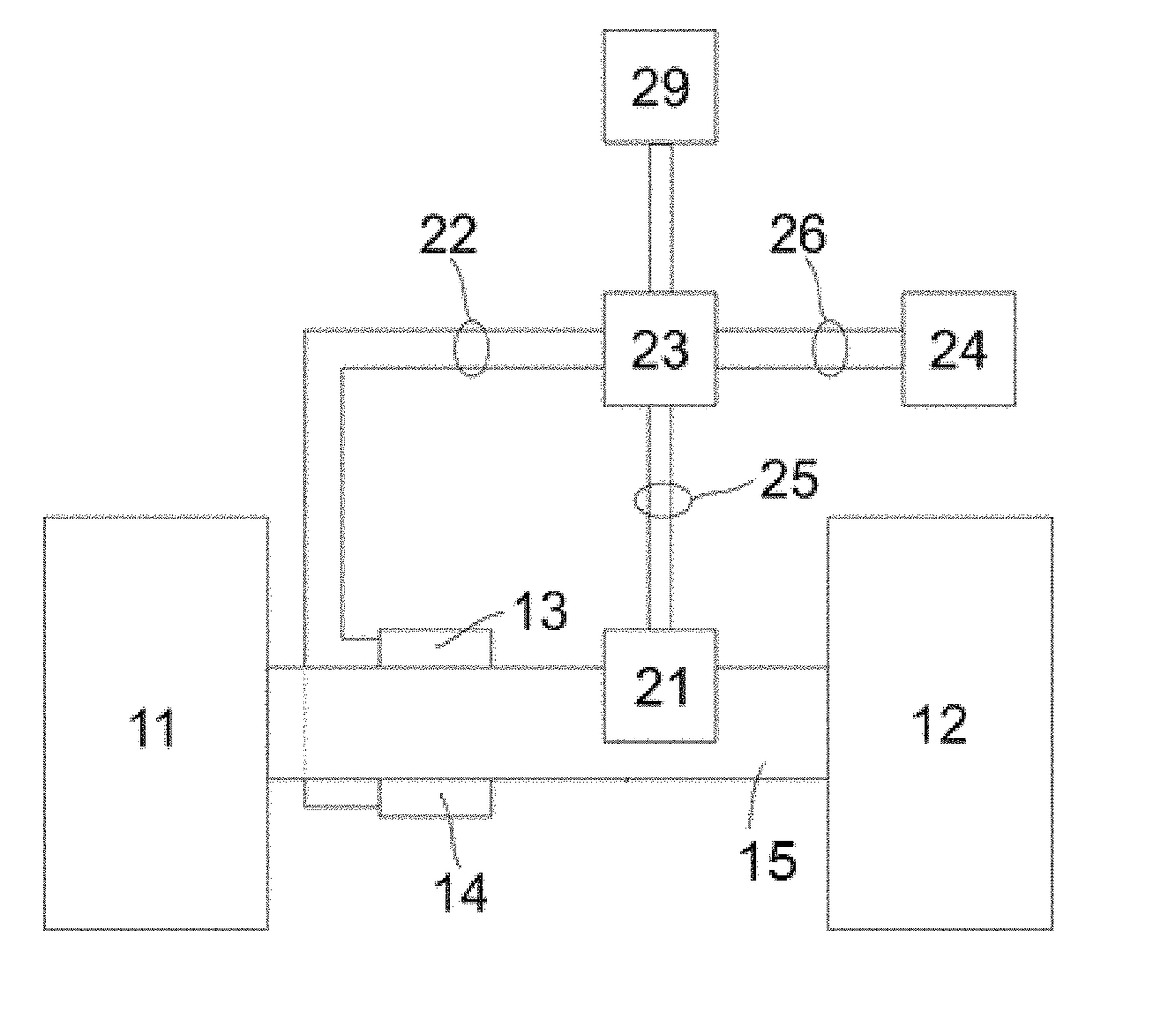
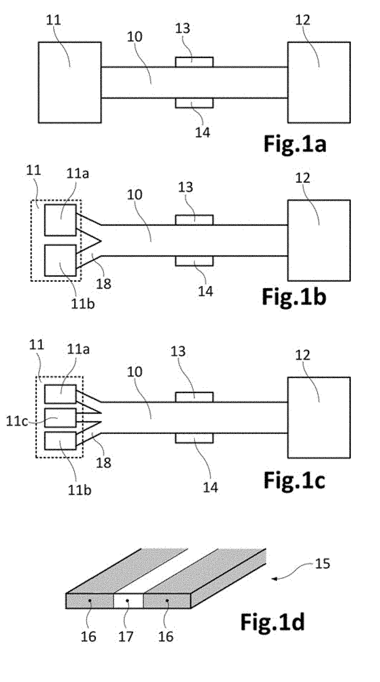
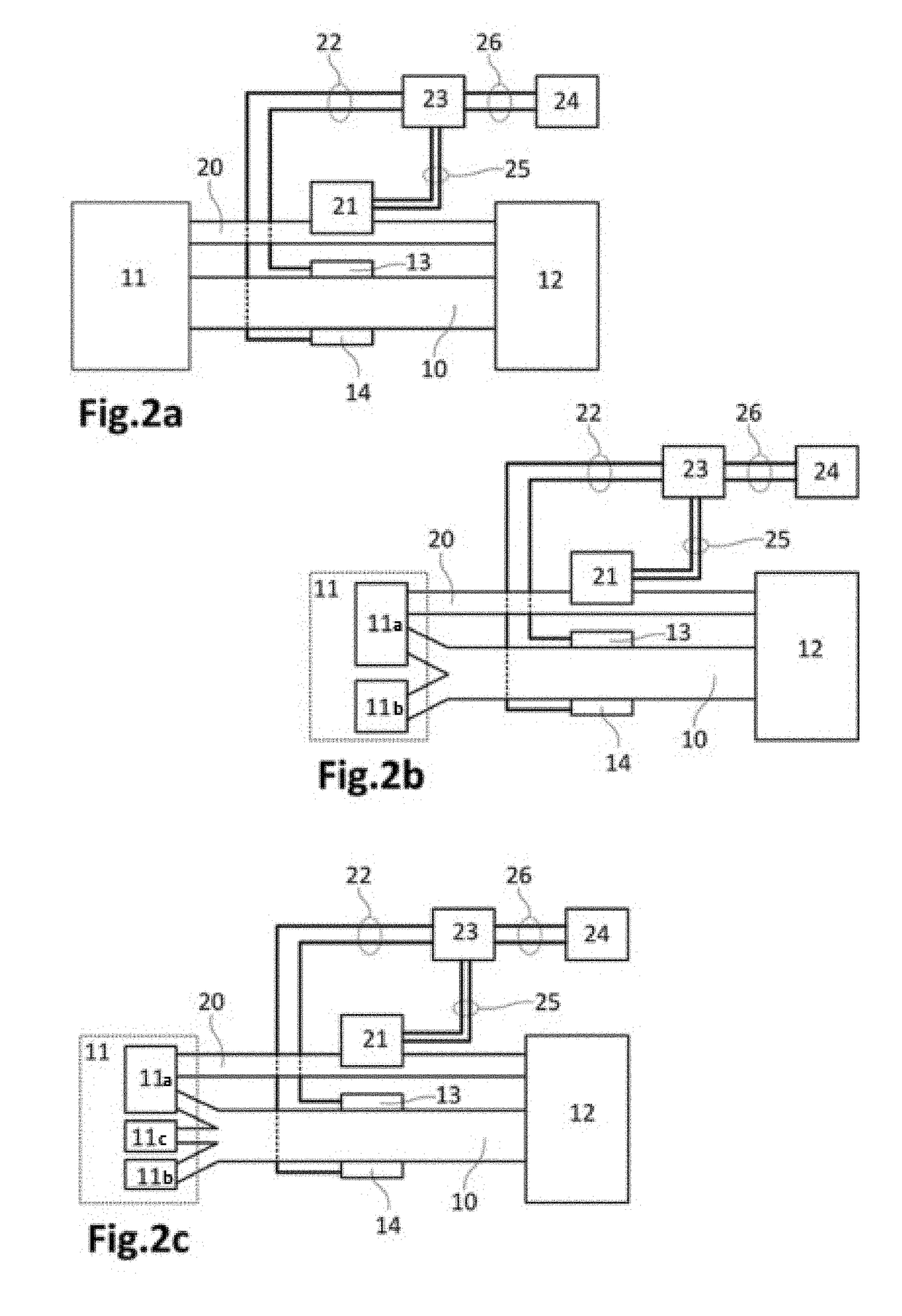
[0009]Embodiments of the present invention provide an analysis device for a liquid sample, preferably a biological sample such as blood, urine, sweat, saliva, tears, sperm, milk, juice, alcoholic drinks, water, etc., that comprises one microfluidic analysis channel made of a wicking material with adequate porosity to allow capillary flow of at least one liquid sample suitable for generating electricity; a receiving absorbent region coupled to said microfluidic analysis channel; a collecting absorbent region coupled to said microfluidic analysis channel; a cathodic zone formed by at least one cathode coupled to said microfluidic analysis channel; an anodic zone formed by at least one anode coupled to said microfluidic analysis channel; and a detection zone including a sensor connected to said microfluidic analysis channel.

[0010]In the proposed analysis device, the receiving absorbent region and the collecting absorbent region are connected to the microfluidic analysis channel, thereb...


PUM


Abstract

An analysis device for a liquid sample comprising: one microfluidic analysis channel made of a wicking material with adequate porosity to allow capillary flow of at least one liquid sample suitable for generating electricity, at least one receiving absorbent region coupled to the microfluidic analysis channel, at least one collecting absorbent region coupled to the microfluidic analysis channel, a cathodic zone coupled to the microfluidic analysis channel, an anodic zone coupled to the microfluidic analysis channel, and at least one detection zone having a sensor, where each receiving absorbent region and each collecting absorbent region are coupled to the microfluidic analysis channel such that when a fluid suitable for generating electricity is deposited in the receiving absorbent region, it flows by capillary action through the microfluidic analysis channel to reach the collecting absorbent region where it is absorbed, and where the sensor interacts with the sample when the latter flows by capillary through the microfluidic analysis channel.

Description

CROSS-REFERENCE TO RELATED APPLICATIONS[0001]This application is a Continuation-in-Part of U.S. application Ser. No. 14 / 409,897, filed on Dec. 19, 2014, the content of which is hereby incorporated by reference in its entirety, which is the national stage entry of International Application No. PCT / EP2013 / 062718, filed on Jun. 19, 2013, the entire disclosures of which are incorporated herein by reference, which claims priority to Spanish Application No. P201230960, filed on Jun. 20, 2012.TECHNICAL FIELD[0002]The present invention is directed, in general, to the field of analysis devices. In particular, the invention relates to an analysis device for a liquid sample. Although preferably the sample to be analysed is a liquid, that it may contain suspended particles, the invention can also analyze a gas sample or a gel.BACKGROUND OF THE INVENTION[0003]A fuel cell is a device that converts chemical energy of a fuel into electrical energy, said conversion takes place as long as the fuel is...

Claims


Application Information

Patent Timeline
IPC IPC(8): B01L3/00H01M8/1286G01J1/04H01M8/16H01M8/04082
CPCB01L3/502715B01L3/502707H01M8/16H01M8/04216G01J1/0403H01M8/1286H01M8/1009H01M8/22B01L2300/0645B01L2300/0867B01L2300/126B01L3/5027B01L2300/0816H01M2250/30Y02B90/10Y02E60/50
Inventor SABATE VIZCARRA, MARIA DE LES NEUSESQUIVEL BOJORQUEZ, JUAN PABLOGASSO-PONS, SERGI
Owner CONSEJO SUPERIOR DE INVESTIGACIONES CIENTIFICAS (CSIC)
Learn More