
Ion implanter, and angle measurement apparatus and beam divergence measurement apparatus for ion implanter

a technology of ion implants and angle measurement, applied in the field of ion implants, can solve the problems of contaminating a substrate, affecting the accuracy of measurement, so as to achieve the effect of enhancing measurement accuracy, enhancing sensitivity, and high accuracy

Inactive Publication Date: 2006-08-31
NISSIN ION EQUIP CO LTD
View PDF3 Cites 10 Cited by
  • Summary
  • Abstract
  • Description
  • Claims
  • Application Information

AI Technical Summary

Benefits of technology

[0012] An object of the invention is to provide an apparatus capable of measuring an angle between a holder and an ion beam at high accuracy, without generating particles, with a simple structure and in a short time even during an ion implantation state. Another object of the invention is to provide an apparatus capable of measuring an actual implantation angle of the ion beam. Further object of the invention is to provide an apparatus capable of obtaining a divergence of the ion beam.

Problems solved by technology

Thus, particles (contaminants) are produced from the Faraday cup during the measurement, which is likely to contaminate a substrate.
Thus, the Faraday cup has a complicated structure, and the measurement takes long time since the elevation of the Faraday cup requires time.
Thus, an angle between the holder and the ion beam can not be measured accurately.
Thus, it is not possible to measure the ion beam in the ion implantation state with the front Faraday unit.

Method used


Image

  • Ion implanter, and angle measurement apparatus and beam divergence measurement apparatus for ion implanter
  • Ion implanter, and angle measurement apparatus and beam divergence measurement apparatus for ion implanter
  • Ion implanter, and angle measurement apparatus and beam divergence measurement apparatus for ion implanter

Examples


Embodiment Construction

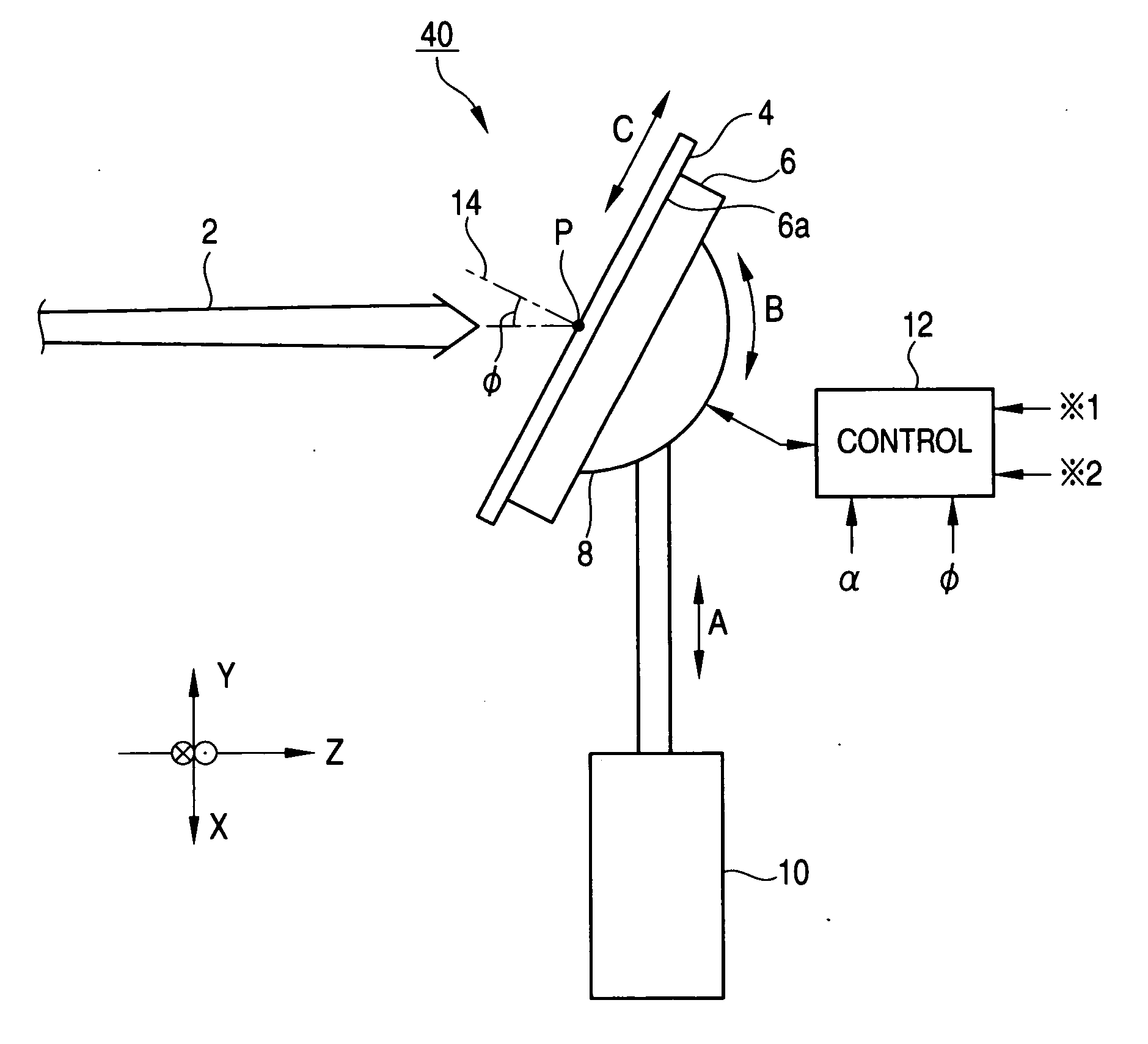
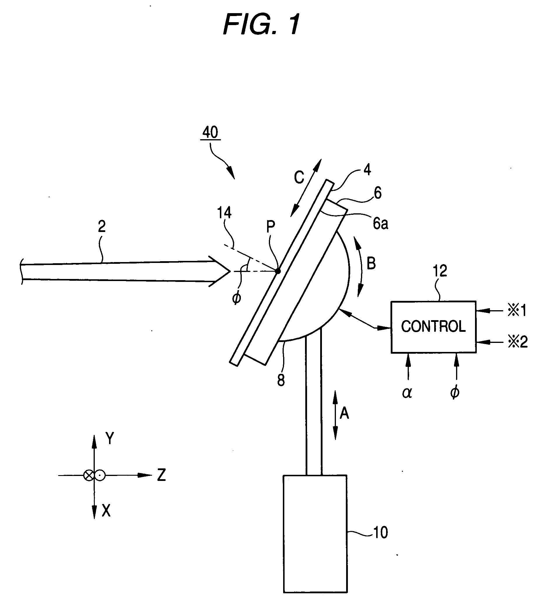
[0054]FIG. 1 is an exemplary side view of a holder and its surroundings of an ion implanter to which a measurement apparatus according to the invention is applicable. An ion implanter 40 is arranged to irradiate an ion beam 2 onto a substrate 4 (for example a semiconductor substrate) which is held by a holder 6 for holding a substrate, so as to perform an ion implantation into the substrate 4, in a vacuum chamber (not shown).

[0055] In this example, assuming that three directions orthogonal to each other at one point are X, Y and Z directions, the ion beam 2 travels in the Z direction and projects onto the substrate 4, while a scanner (not shown) performs scanning with the ion beam 2 reciprocating in the X direction. The holder 6 and the substrate 4 thereon are mechanically driven up and down in the Y direction by a holder driving device 10 as shown by an arrow A. The ion beam 2 is thus irradiated onto the entire surface of the substrate 4, and the ion implantation is performed. In ...


PUM


Abstract

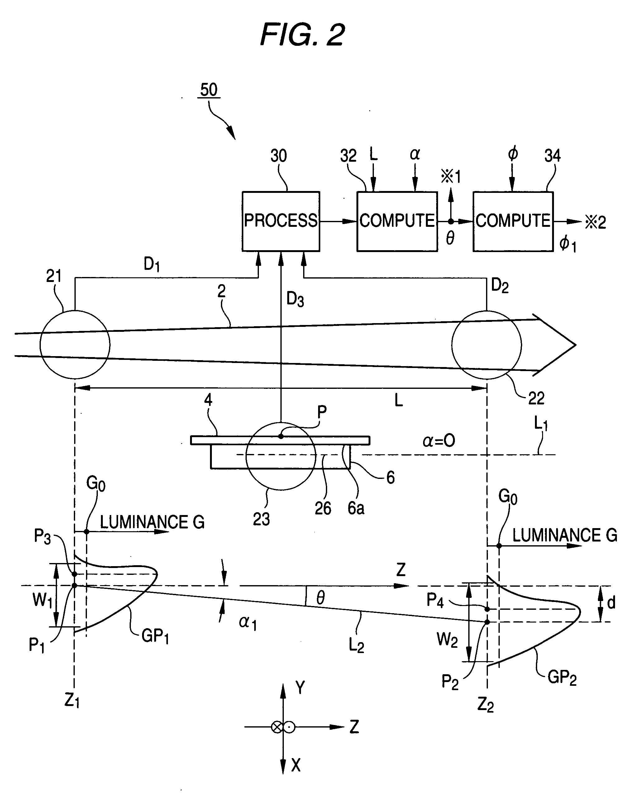
An apparatus is provided which is capable of measuring an angle between a holder and an ion beam without generating particles, with a simple structure, in a short time and at high accuracy even during an implantation state. An angle measurement apparatus is configured to: measure an angle of the ion beam by measuring beam plasma produced and emitting light when the ion beam collides with residual gas, with two cameras at two positions in a beam traveling direction; measure an angle of the holder by measuring light from a linear light source provided on the holder; and thereby measure the angle between the ion beam and the holder.

Description

[0001] This application claims foreign priority based on Japanese Patent application No. 2005-009078, filed Jan. 17; 2005, the contents of which is incorporated herein by reference in its entirety. BACKGROUND OF THE INVENTION [0002] 1. Field of the Invention [0003] The present invention relates to an angle measurement apparatus for measuring an angle between a holder holding a substrate and an ion beam, and an actual implantation angle of the ion beam, etc., the angle measurement apparatus being used for an ion implanter. The present invention also relates to the ion implanter having the angle measurement apparatus, and a beam divergence measurement apparatus for measuring a divergence of the ion beam. [0004] 2. Description of the Related Art [0005] A related art ion implanter, for example, as described in JP-A-2001-143651 (paragraphs 0002-0007, FIG. 5), uses a front Faraday unit (multipoint Faraday cup) capable of being elevated and lowered, the Faraday unit being arranged on an up...

Claims


Application Information

Patent Timeline
IPC IPC(8): G21G5/00
CPCH01J37/304H01J37/3171G06T7/70G01B11/26H01J37/222E04B2/06E04B2/44E04B2002/0243
Inventor YAMASHITA, TAKATOSHI
Owner NISSIN ION EQUIP CO LTD
Learn More