Shaft and shaft molding device

a molding device and shaft technology, applied in the direction of manufacturing tools, branching pipes, mechanical equipment, etc., can solve the problems of heavy processing load, different firmly fixing, excessive processing load, etc., and achieve the effect of maintaining the roundness of the member to be fitted, improving the fixing strength of the shaft, and easy matching

Inactive Publication Date: 2006-08-31
MITSUBA CORP
View PDF19 Cites 7 Cited by
  • Summary
  • Abstract
  • Description
  • Claims
  • Application Information

AI Technical Summary

Benefits of technology

[0028] Further, according to the present invention, since the eight strips of knurls are circumferentially arranged and disposed, the fixing strength thereof can be improved while the roundness of the member to be fitted is maintained. Also, after the four strips of knurls are formed, the shaft is circumferentially rotated by 45 degrees and is processed again, so that the eight strips of knurls can be easily formed.
[0029] Further, according to the present invention, since the positions of the pair of molding edges adjacent to each other with respect to the shaft can be easily matched, accuracy of assembling the molding apparatus of the shaft can be improved.
[0030] Further, according to the present invention, since the knurls are circumferentially formed evenly, a section of the shaft becomes a substantially complete-round shape, so that variations of the loads applied to the member to be fitted in press-inserting the shaft can be decreased.

Problems solved by technology

However, in such a method, since an inner diameter of the fit hole is formed slightly larger than an outer diameter of the shaft, firmly fixing is different.
However, such a molding apparatus needs a heavy processing load since the extrusion face of each molding edge is formed orthogonally to the cutting face.
Particularly, when a distance between the adjacent molding edges is set short, an angle formed between each extrusion face and the outer circumferential surface of the shaft becomes small and thereby an excessive processing load becomes necessary.
Additionally, when the commutator is deformed into an ellipse, cutting margins change in cutting the outer circumferential surface and therefore there is a problem of an occurrence etc. of cutting remains of the coating material.
Moreover, by biases of positions of the knurls, a weight balance of the shaft itself is biased, and this becomes a cause for an occurrence of vibrations generated in rotating the armature shaft.

Method used


Image

  • Shaft and shaft molding device
  • Shaft and shaft molding device
  • Shaft and shaft molding device

Examples


Embodiment Construction

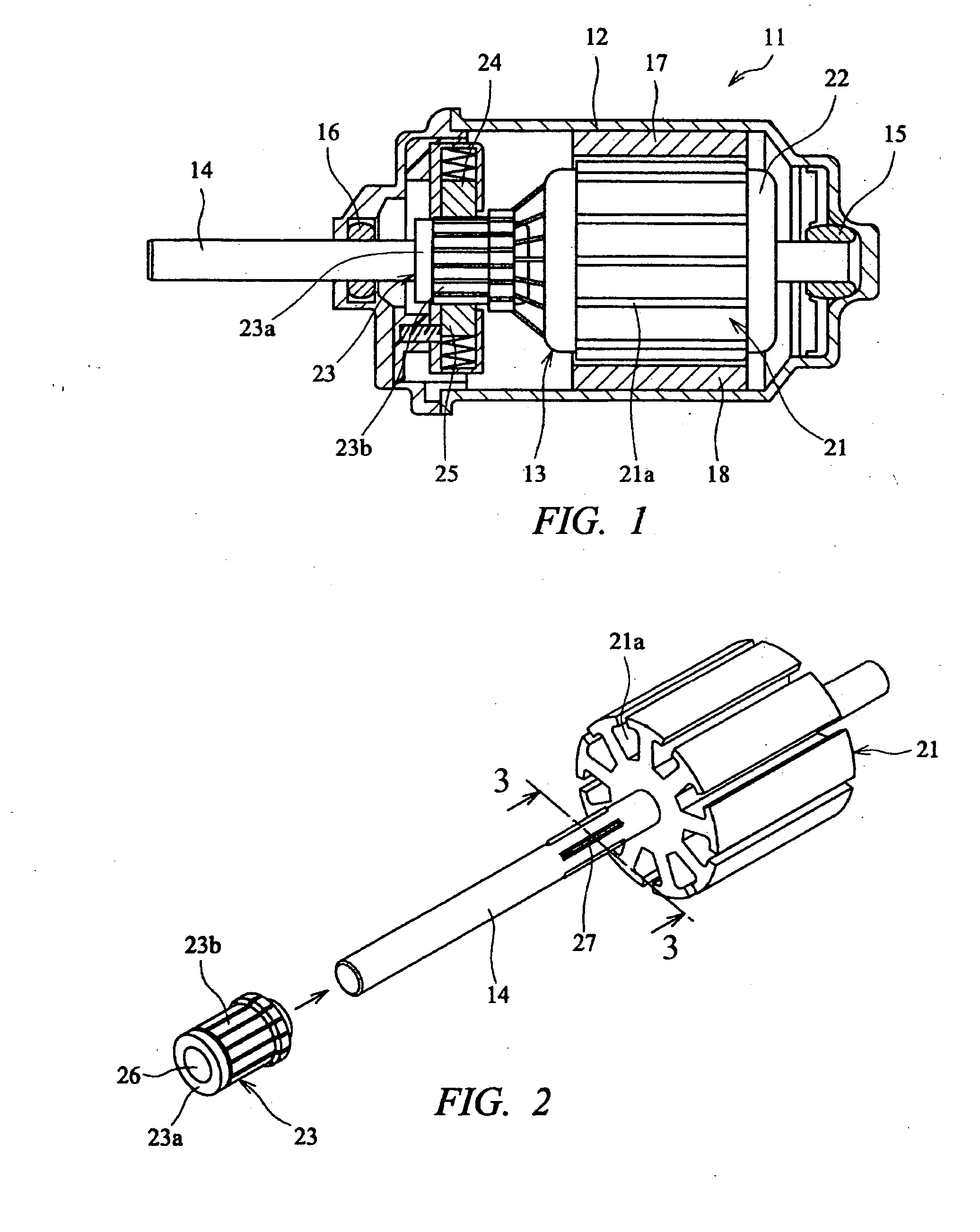
[0041] As shown in FIG. 1, an electric motor 11 has an armature 13 accommodated in a motor housing 12.

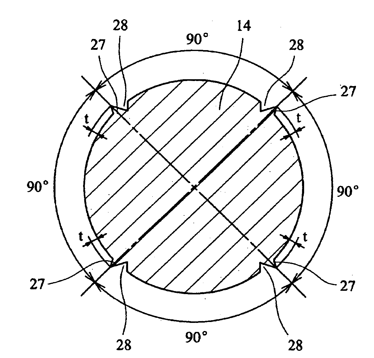
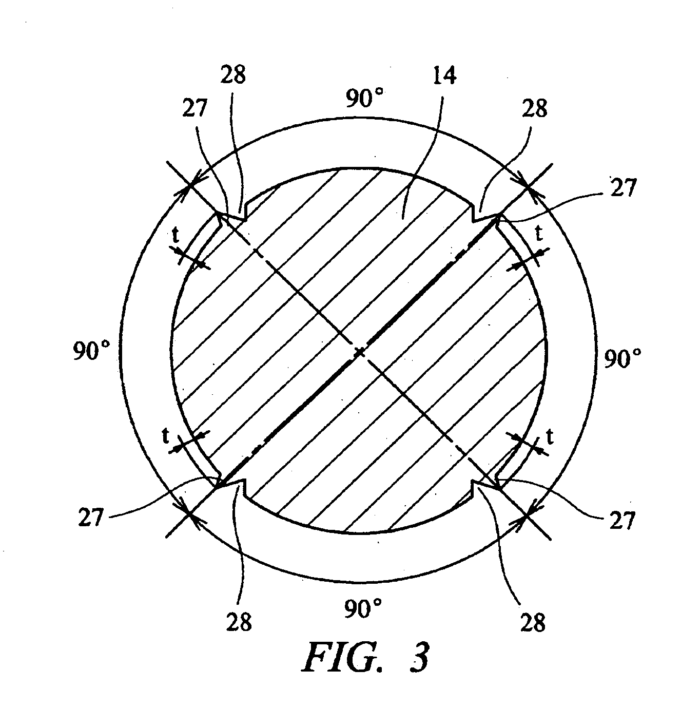
[0042] The armature 13 is made of steel and has an armature shaft 14 serving as a shaft formed into a substantially circular and uniform section and this armature shaft 14 is supported by bearings 15 and 16, thereby becoming rotatable inside the motor housing 12.

[0043] An armature core 21, which is located within a magnetic field created by a pair of permanent magnets 17 and 18 fixed to the motor housing 12, is fixed to the armature shaft 14. An armature coil 22 is wound around each of a plurality of slots 21 a formed in the armature core 21.

[0044] Also, a commutator serving as a member to be fitted is fixed to the armature shaft 14. The commutator 23 comprises: a body portion 23a made of a resin; and a plurality of commutator segments 23b arranged radially on and fixed to an outer circumferential surface of the body portion 23a, wherein the armature coil 22 is connected to each ...


PUM

PropertyMeasurementUnit
angleaaaaaaaaaa
angleaaaaaaaaaa
angleaaaaaaaaaa

Abstract

Four knurls are formed by a molding apparatus (31) to be evenly spaced circumferentially on and protrude from an outer circumferential surface of an armature shaft (14). The molding apparatus (31) has a first mold (32) and a second mold (33), which are movable in directions of being close to and separating from each other, wherein the first mold (32) is provided with a pair of first molding edges (43) and the second mold (33) is provided with a pair of second molding edges (45). The respective molding edges (43) and (45) are formed into parallelogram sections, which have cutting faces (51) and (61) parallel to a moving direction of the second mold (33), extrusion faces (52) and (62) formed at acute angels with respect to the cutting faces (51) and (61), and load supporting faces (53) and (63) parallel to the extrusion faces (52) and (62). By pressing those molding edges (43) and (45) against the outer circumferential surface of the armature shaft (14), the knurls is formed.

Description

CROSS-REFERENCE TO RELATED APPLICATIONS [0001] This application is entitled to the benefit of and incorporates by reference essential subject matter disclosed in International Patent Application No. PCT / JP2004 / 002363 filed on Feb. 27,2004 and Japanese Patent Application No. 2003-050726 filed on Feb. 27, 2003.FIELD OF THE INVENTION [0002] The present invention relates to a shaft, which has knurls formed for being firmly fitted / fixed to a member to be fitted on an outer circumferential surface of the shaft. BACKGROUND OF THE INVENTION [0003] Since conventionally, a method of press-inserting a shaft into a fit hole formed in a member to be fitted and fitting / fixing the member to be fitted to the shaft has been known. However, in such a method, since an inner diameter of the fit hole is formed slightly larger than an outer diameter of the shaft, firmly fixing is different. Therefore, the conventional fixing method is such that a plurality of strips of knurls, each of which protrudes fro...

Claims


Application Information

Patent Timeline
Patent Type & Authority Applications(United States)
IPC IPC(8): B25G3/00B21J5/12B21K1/12
CPCB21J5/12Y10T403/4674B21K1/12B21K1/066F16B2200/40
Inventor YOKOO, TSUGIONANBA, YOSHIHIRO
Owner MITSUBA CORP
Why Eureka
Try Eureka